Clutch mechanism for locks

a technology of locking mechanism and locking mechanism, which is applied in the direction of mechanical control devices, keyhole guards, instruments, etc., can solve the problems of complex executions in the configuration, number and assembly of pieces, and achieve the effect of facilitating assembly

Inactive Publication Date: 2005-01-04
TALLERES DE ESCORIAZA SA
View PDF14 Cites 34 Cited by
  • Summary
  • Abstract
  • Description
  • Claims
  • Application Information

AI Technical Summary

Benefits of technology

This structure ensures that the turning of the interior axis from its resting position causes the movable actuator to be pushed toward the outside of the static body producing the activation of the micro-switch from which will result an electrical signal which reflects the position of this movable activator and which, as a function of this, can be used for functions complementary to the locking system or to the clutch itself. In addition, the housing itself of the head of the movable activator in the recess of the interior axis helps to mark a position which facilitates assembly and favors the precise adoption of the resting state in which the change between the disengaged and engaged states of the proposed mechanism must take place.

Problems solved by technology

The result is the production of executions which are complex in the configuration, number and assembly of the pieces and which are only valid in themselves.

Method used


Image

  • Clutch mechanism for locks
  • Clutch mechanism for locks
  • Clutch mechanism for locks

Examples


Embodiment Construction

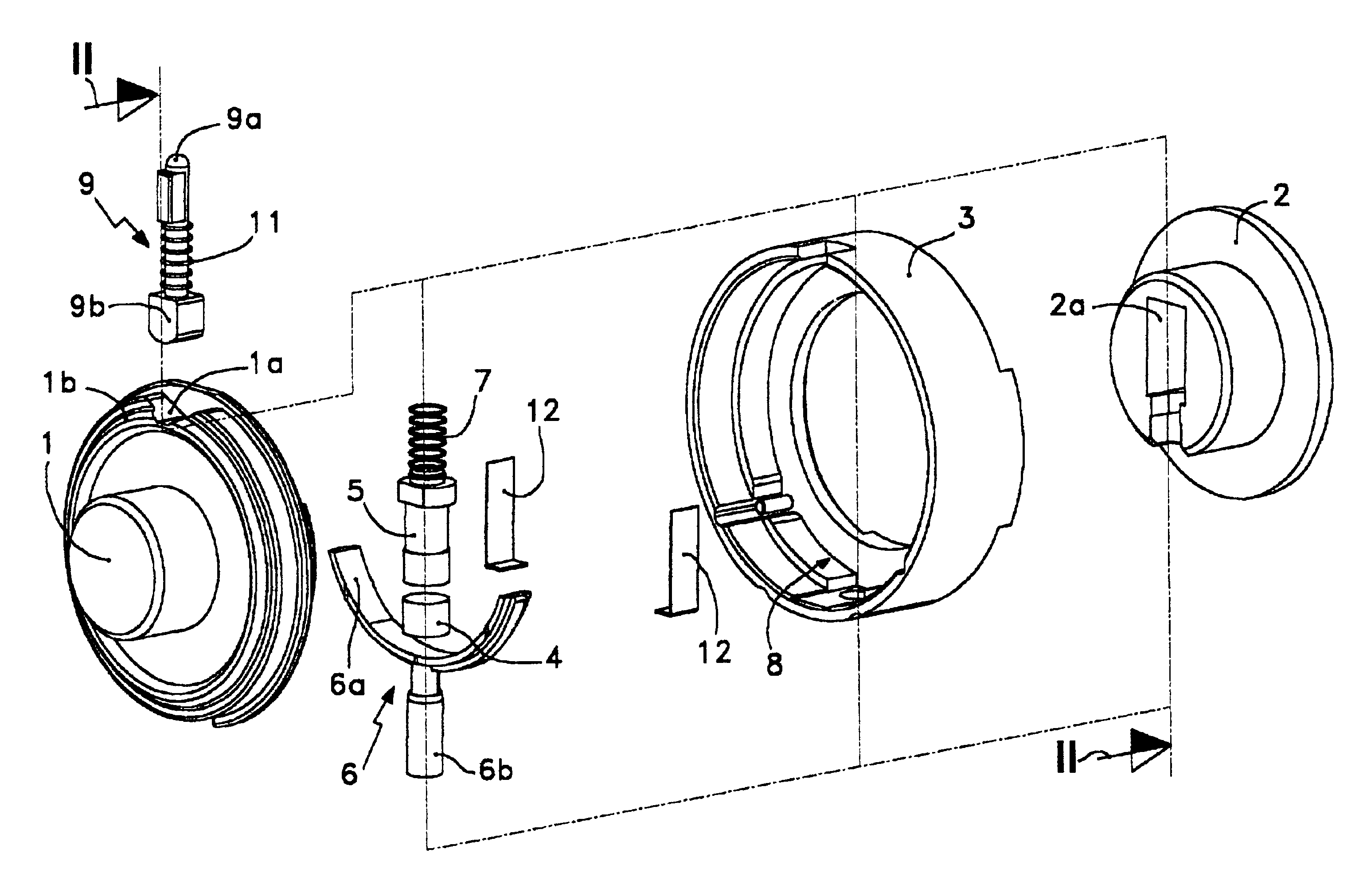
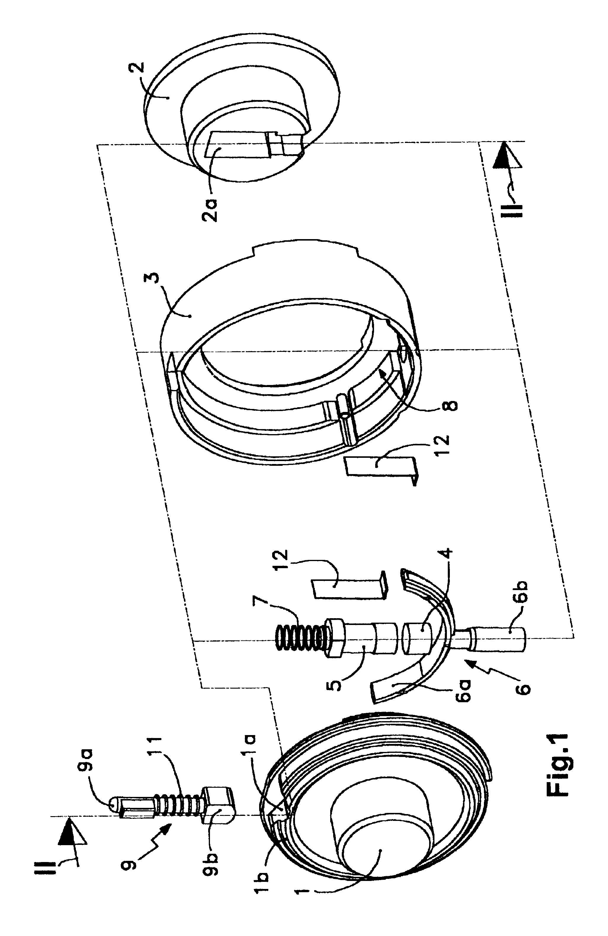
With relation to the drawings and references enumerated above, a preferred mode of execution of the proposed clutch mechanism for locks is illustrated in the attached plans.

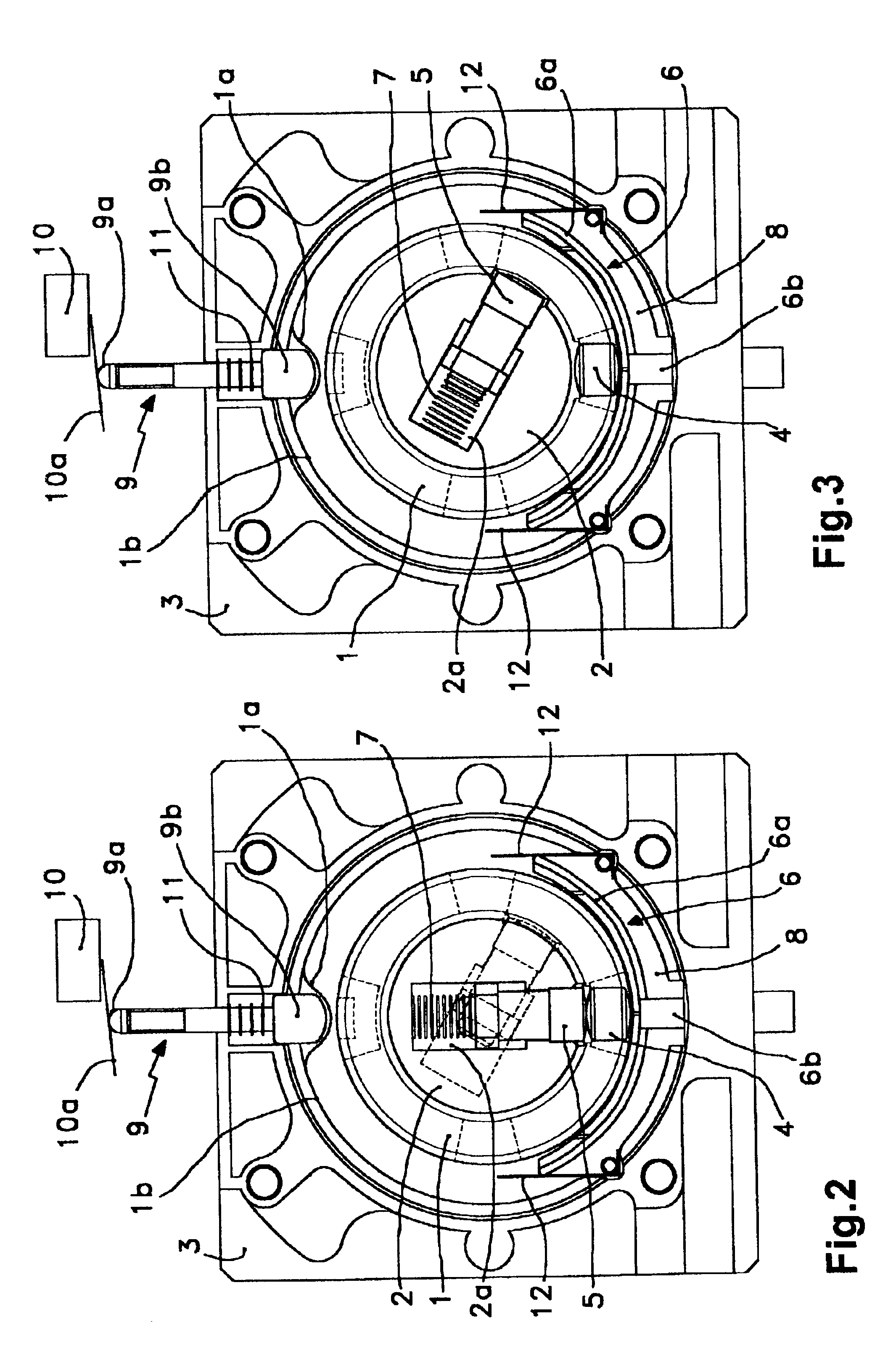
As shown in FIG. 1, this mechanism is composed of an interior axis (1), an exterior axis (2), a static body (3), a set of radial pin (4) and radial catch (5) and a radial actuator (6); in which: said interior axis (1), exterior axis (2) and static body (3) compose a coaxial assembly in which the exterior axis (2) penetrates with a rotational adjustment within the interior axis (1) when both the interior (1) and exterior (2) axes are installed with a rotational adjustment in the static body (3), said set of radial pin (4) and radial catch (5) is installed with a movable adjustment between said actuator (6) which is in contact with the radial pin (4) and a radial compression spring (7) which acts between the radial catch (5) and the base of a housing (2a) of the exterior axis (2), whose radial pin (4) and radial ca...


PUM


Abstract

Clutch mechanism for locks, which is composed of an interior axis (1), an exterior axis (2), a static body (3), a radial pin (4), a radial catch (5) and a radial actuator (6); said interior (1) and exterior (2) axes and body (3) compose a coaxial assembly where the exterior axis (2) penetrates the interior axis (1) and both are installed with a rotational adjustment in the static body (3), the set of radial pin (4) and radial catch (5) is installed between the actuator (6) and a radial spring (7) which acts between the catch (5) and the base of the housing (2a) of the exterior axis (2); whose pin (4) and catch (5) are dimensioned in such a way that each will be able to be moved between the circumferences of the exterior diameter of the axis (2) and the interior diameter of the axis (1); the radial actuator (6) is composed of a curved plate (6a) and by, at least, one rod (6b), whose plate (6a) is located in an annular depression (8) between the interior axis (1) and static body (3), extending in a circumferential arc containing the angular sector corresponding to the operative rotational transit of the interior axis (1).

Description

FIELD OF THE INVENTIONThe present invention refers to a clutch mechanism which has the objective of facilitating the selective rotational coupling between primary and secondary axes, so that it can be determined as desired that one of them, for example the primary axis, may or may not be rotationally pulled by the turning of the other axis, for example the secondary axis.This mechanism is specially designed for locks, and deals with those of the mechanical as well as the electromechanical type.In the following, we consider that the primary axis is the one which is on the inside of the lock and is designated the “interior axis”, and that the secondary axis is the one which is on the outside of the lock and is designated the “exterior axis”.BACKGROUND OF THE INVENTIONA characteristic feature of the manufacture of locks is that they respond to highly individualized designs including those created by a single manufacturer. This means that each lock responds to an exclusive design which ...

Claims


Application Information

Patent Timeline
Patent Type & Authority Patents(United States)
IPC IPC(8): E05B47/06E05B13/00E05B63/00E05B63/16
CPCE05B47/0692E05B13/005E05B63/16Y10T70/5677Y10T70/5805Y10T70/5823
Inventor RUANO ARAMBURU, LUIS ANGELMENTA SANMIGUEL, FERMIN
Owner TALLERES DE ESCORIAZA SA
Why Eureka
Try Eureka