Unitary boom structure

a boom and unitary technology, applied in the direction of girders, ways, applications, etc., can solve the problems of uneven or unpredictable level of spraying of liquid to the crop, nozzles to physical damage, and liquid mist or droplets to be disturbed, so as to increase the efficiency and accuracy of spraying apparatus

Inactive Publication Date: 2005-01-04
JESSE LYNN
View PDF21 Cites 33 Cited by
  • Summary
  • Abstract
  • Description
  • Claims
  • Application Information

AI Technical Summary

Benefits of technology

to provide a sprayer boom constructed in such a way that nozzles delivering liquid are better prote

Problems solved by technology

In addition, other sprayer booms often position the nozzles in a manner that creates a vulnerability of the liquid mist or droplets to disturbance by wind or of the nozzles to physical damage.
Such disturbance results in an uneven or un

Method used


Image

  • Unitary boom structure
  • Unitary boom structure
  • Unitary boom structure

Examples


first embodiment

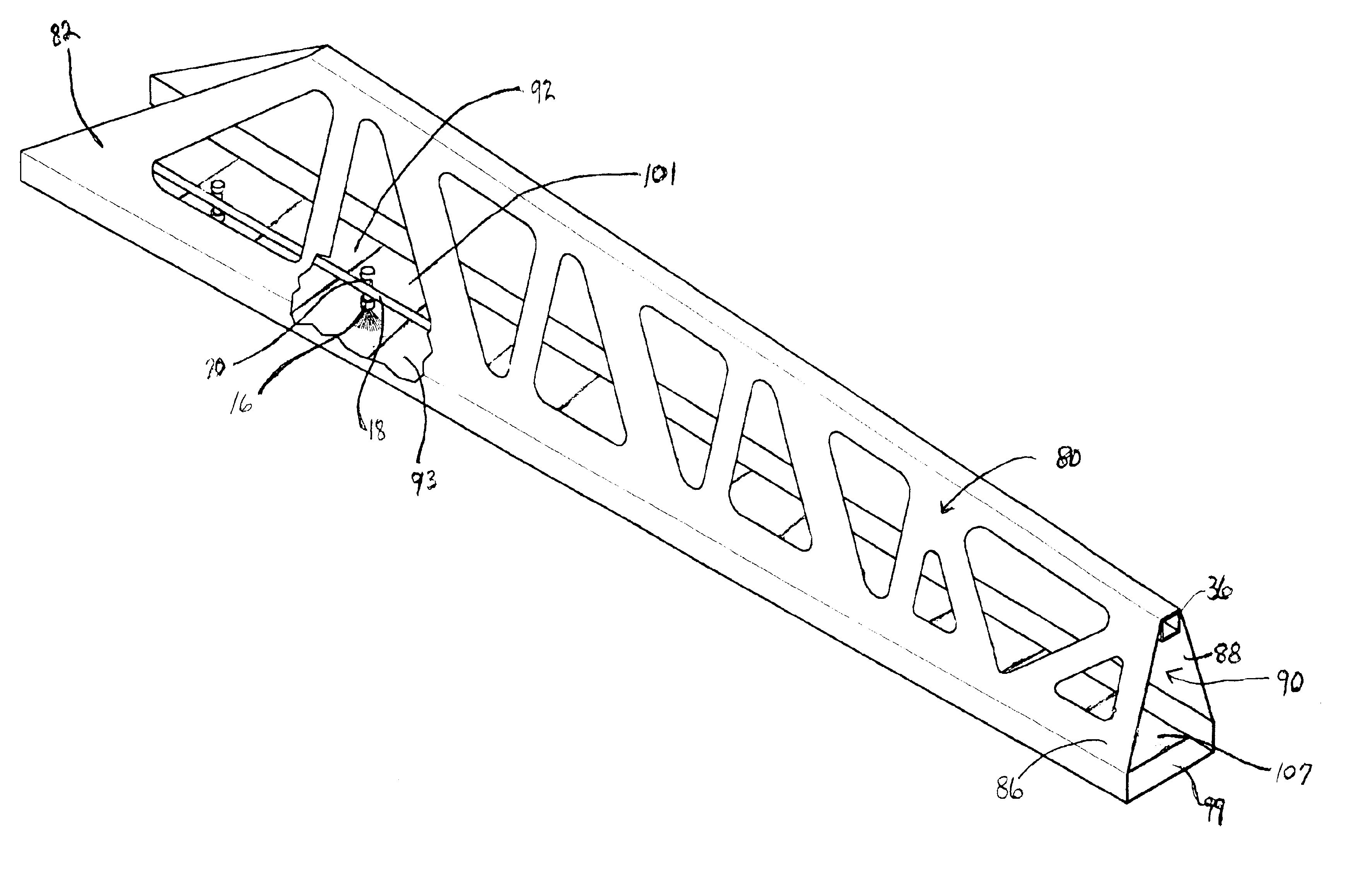
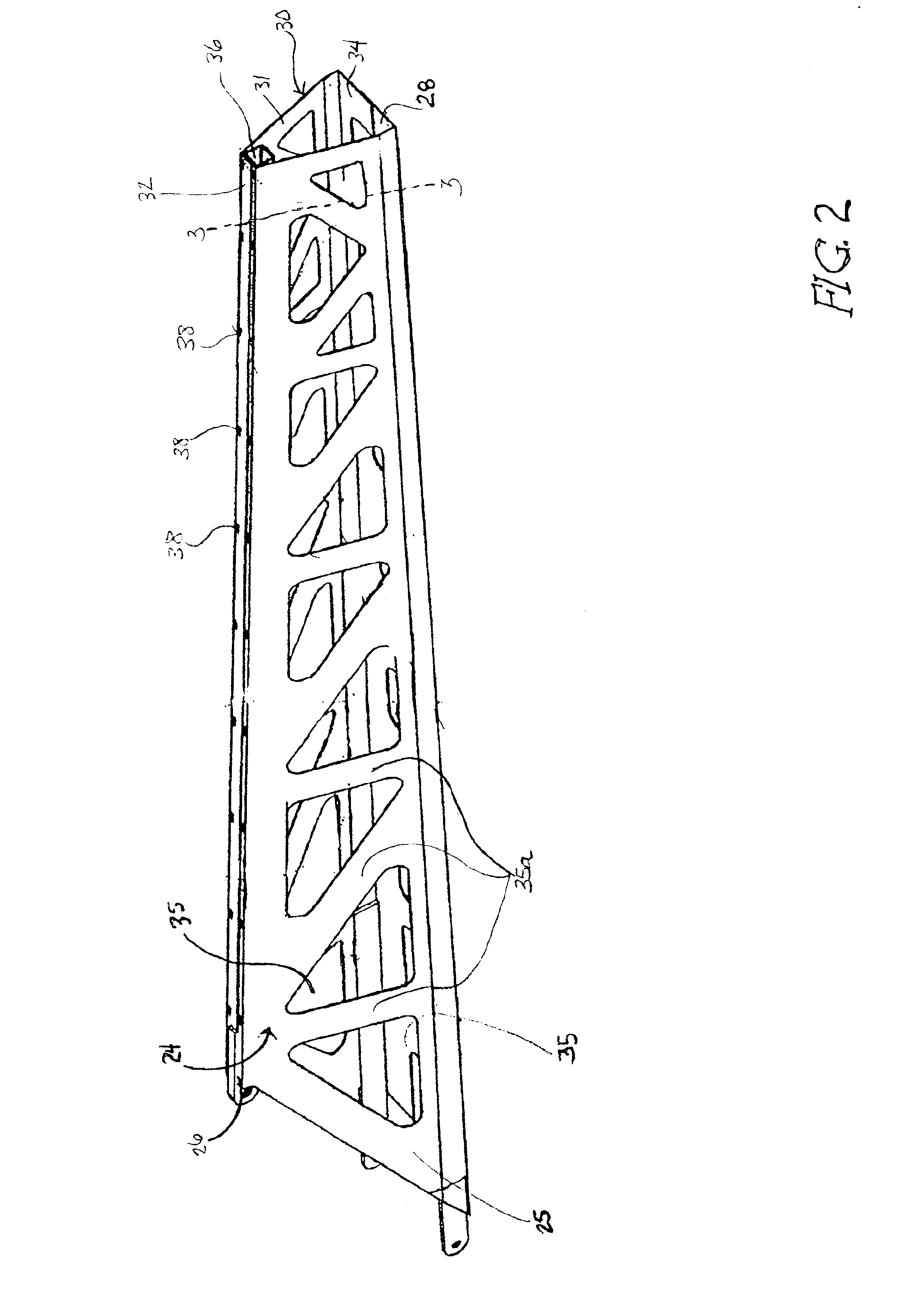
the present invention comprises a first single-piece component 24 with a side surface 25, a top flange 26 and a bottom flange 28, a second single-piece component 30 with a side surface 31, a top flange 32 and a bottom flange 34, a carrier beam 36, and means 38 for associating said first single-piece component 24 and said second single-piece component 30 with said carrier beam 36. These elements are shown in FIGS. 2-4.

Referring now especially to FIG. 2a, said side surfaces 25 and 31 of said single piece components, 24 and 30, respectively, include a series of triangular openings 35 wherein each opening is an inverted triangle relative to the openings on either side of it and struts 35a are left between the openings to provide support. Such arrangement results in a web or truss structure which looks and functions in the manner of a series of trusses often seen on bridges and crane booms and similar to other sprayer booms, however, the single-piece components 24 and 30 of sprayer boom ...


PUM


Abstract

The present invention comprises a sprayer boom and is incorporated in a spraying apparatus which includes a vehicle, a tank, hoses connected to nozzles, and the sprayer boom. The sprayer boom includes a number of wing sections each including at least one single-piece component cut from a sheet of metal to form a web or truss structure which replaces the usual rods and welds support provided to sprayer booms of this nature. Obtaining the single-piece component by cutting it from a sheet of metal rather than constructing the truss-structure by use of many rods reduces material and labor costs. Spaced apart rungs or tabs on the bottom of the sprayer boom provide openings through which sprayer nozzles are aimed while the nozzles, hoses and connectors remain mostly recessed within the boom which provides physical protection from wind and other damage and still allows easy access for repair.

Description

BACKGROUND OF THE INVENTION1. Field of the InventionThe present invention relates in general to a device used to apply liquid herbicides, nutricides or pesticides to crops and, more specifically, to a sprayer boom through which the liquid is applied.2. Description of the Prior ArtIt is known in the art to use herbicides, nutricides and pesticides in dry or liquid form to improve the health of plants. Liquid form is often applied using a spraying apparatus by positioning a nozzle in the apparatus over a plant or group of plants and forcing the liquid through the nozzle such that it is dispersed in a mist or fine droplets. When using this type of apparatus on a field crop, it must be mounted on or otherwise attached to a tank which holds the liquid and a conveyance vehicle in order to provide a continuous mist or droplets and move it over and through the crop. Quite often, the spraying apparatus includes a sprayer boom on which nozzles are mounted and which extends beyond the width of...

Claims


Application Information

Patent Timeline
IPC IPC(8): A01M7/00A01C23/00B05B13/00
CPCA01C23/008A01M7/0071A01M7/006B05B13/005
Inventor JESSE, LYNN
Owner JESSE LYNN
Why Eureka
Try Eureka