Electrostatically actuated valve

a technology of electric actuator and valve body, applied in the direction of valve details, valve arrangement, circuit elements, etc., can solve the problems of large size and weight, large voltage and/or power requirements, and many significant shortcomings, and achieve the effect of consuming relatively low voltage and/or power and low fabrication costs

Inactive Publication Date: 2005-01-04
HONEYWELL INT INC
View PDF80 Cites 98 Cited by
  • Summary
  • Abstract
  • Description
  • Claims
  • Application Information

AI Technical Summary

Benefits of technology

The present invention provides an electrostatically actuated valve that is relatively small, has relatively low fabrication costs, and consumes relatively low voltage and / or power. Normally closed, normally open and three (or more) way valve configurations are shown for illustrative purposes, but other configurations are contemplated and are within the scope of the present invention. The electrostatically actuated valves of the present invention are suitable for a wide variety of applications, including wireless applications.

Problems solved by technology

While some prior art valves perform satisfactory for some applications, many have significant shortcomings including a relatively large size and weight, a relatively large voltage and / or power requirement, a relatively high fabrication cost, and / or other shortcomings.

Method used


Image

  • Electrostatically actuated valve
  • Electrostatically actuated valve
  • Electrostatically actuated valve

Examples


Embodiment Construction

The following description should be read with reference to the drawings wherein like reference numerals indicate like elements throughout the several views. The detailed description and drawings are presented to show embodiments that are illustrative of the claimed invention.

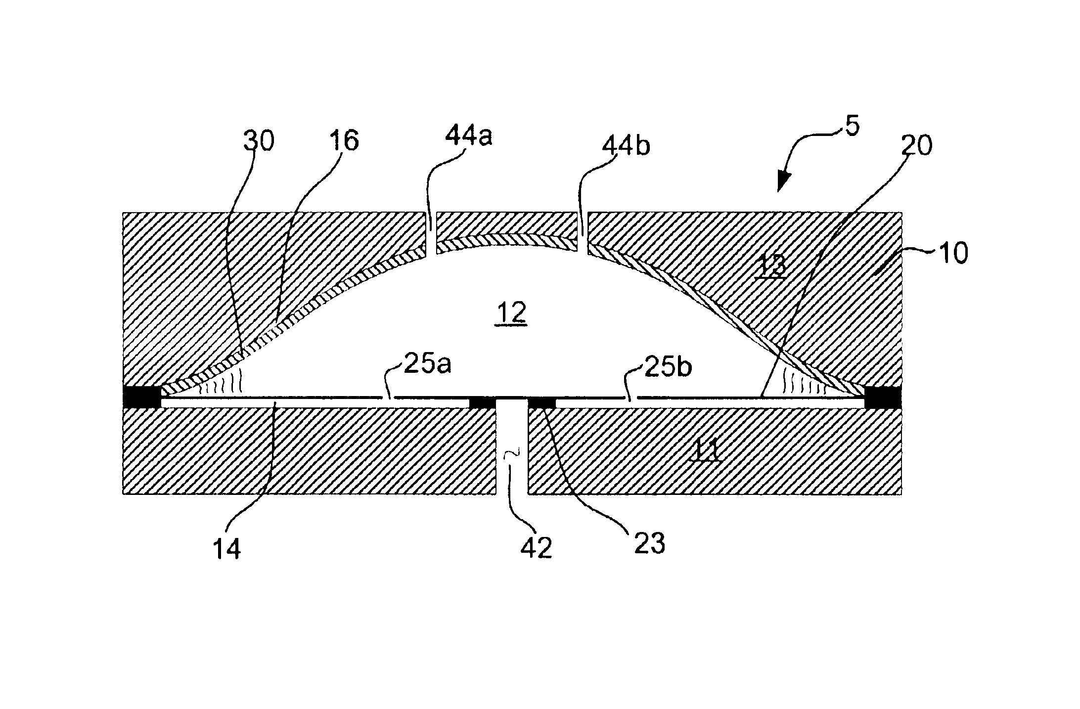
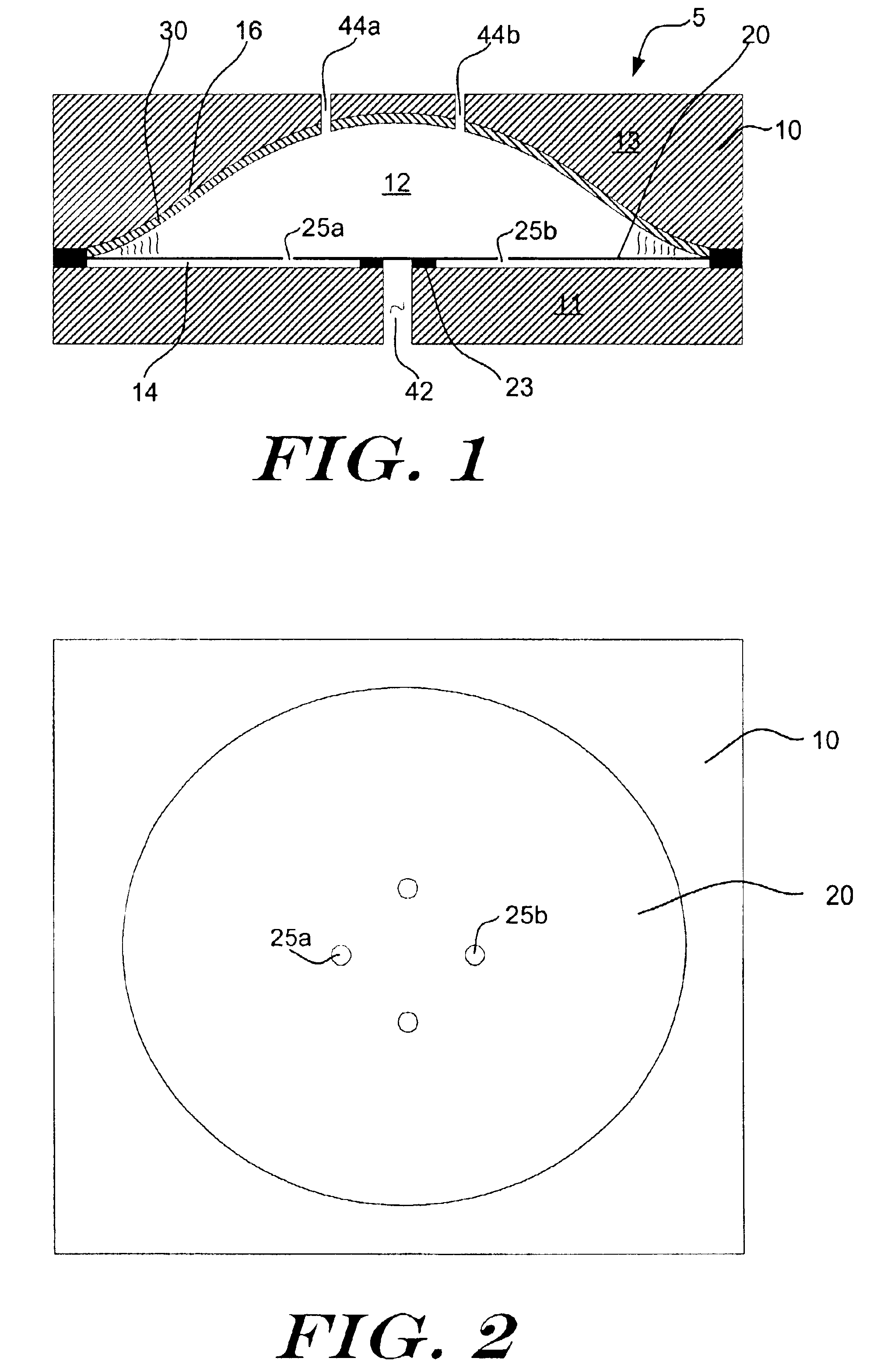
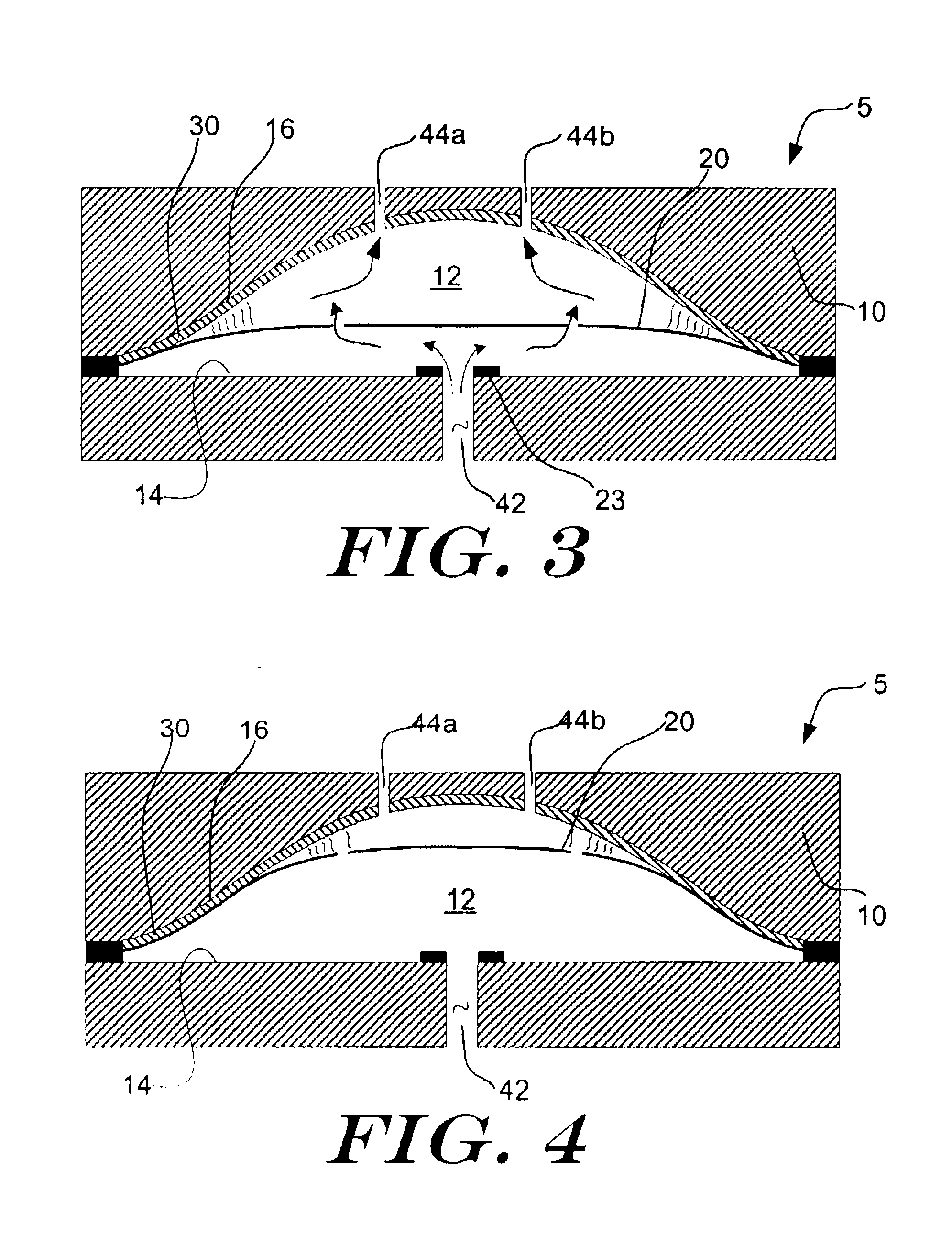
FIG. 1 is a cross-sectional side view of an illustrative normally closed valve in accordance with the present invention. The valve is generally shown at 5, and has a body 10 with a first opposing wall 14 and a second opposing wall 16 that define a valve chamber 12. In the illustrative embodiment, a first port 42 (e.g. inlet port) extends into the valve chamber 12 through the first opposing wall 14. One or more second ports (e.g. outlet ports), such as ports 44a and 44b, extend into the valve chamber 12 through the second opposing wall 16.

A diaphragm 20 is mounted within the chamber 12. In some embodiments, this may be accomplished by sandwiching the diaphragm 20 between an upper body portion 13 and a lower body ...


PUM


Abstract

An electrostatically actuated valve that is relatively small, has relatively low fabrication costs, and consumes relatively low voltage and/or power. Normally closed, normally open, three (or more) way valves, and other configurations are contemplated. These electrostatically actuated valves are suitable for a wide variety of applications, including but not limited to, low power and wireless applications, for example.

Description

BACKGROUNDThe present invention generally relates to electro-pneumatic transducers, and more particularly, to electrostatically actuated valves.Many industrial, commercial, aerospace, military and other applications depend critically on reliable valves for fluid (including gas) handling. In a chemical plant, for example, valves are often used to control the flow of fluid throughout the facility. Likewise, in an airplane, valves are often used to control air and fuel delivery, as well as some of the hydraulic systems that drive the control surfaces of the airplane. These are just a few examples of the many applications that depend critically on reliable valves for fluid (including gas) handling.In many cases, one or more main valves are used to directly control the fluid. In other cases, smaller control or pilot valves are used to control the operation of a main valve. In any cases, it is often desirable to minimize the power and / or voltage required to operate the main and / or pilot v...

Claims


Application Information

Patent Timeline
Patent Type & Authority Patents(United States)
IPC IPC(8): F15C5/00F16K31/02F16K99/00
CPCF15C5/00F16K31/02F16K99/0051F16K99/0015F16K99/0028F16K99/0001Y10T137/86879Y10T137/87788
Inventor CABUZ, CLEOPATRACABUZ, EUGEN I.
Owner HONEYWELL INT INC
Why Eureka
Try Eureka