
Ploughs

Inactive Publication Date: 2005-01-04
IHC ENGINEERING BUSINESS LIMITED
View PDF15 Cites 15 Cited by
  • Summary
  • Abstract
  • Description
  • Claims
  • Application Information

AI Technical Summary

Benefits of technology

A third aspect of the present invention provides a plough comprising a plough share and a tow rope attachment mechanism having a pair of bridle limb attachment points, the tow rope attachment mechanism being adapted to enable movement of the bridle limb attachment points relative to the plough, thereby altering the position at which the line of a tow rope connected to the bridle limbs crosses the longitudinal axis of the plough, so that the plough can operate at a range of offset tow positions, and further comprising a mechanical linkage between the bridle limb attachment points such that movement of one bridle limb attachment point in one sense is accompanied by movement of the other in the other sense.
A fourth and related aspect of the invention provides a plough comprising a plough share and a tow rope attachment mechanism having a pair of bridle limbs, the tow rope attachment mechanism being adapted to enable adjustment of the relative length of the bridle limbs, thereby altering the position at which the line of a tow rope connected to the bridle limbs crosses the longitudinal axis of the plough, so that the plough can operate at a range of offset tow positions, and further comprising a mechanical linkage between the bridle limbs such that lengthening of one bridle limb is accompanied by shortening of the other.

Problems solved by technology

This method of steering a plough has the disadvantage that the direction of travel of the plough is affected by changes in the tow rope direction together with any side forces, for example from side slopes that the plough may be traversing.
This method of steering has the disadvantage that without such a force minimisation towing mechanism the steering angles relative to the tow rope are limited.
Also the force minimisation towing mechanism described would be difficult to adapt for larger angles of steering because of the requirement for a mechanism of greater size.
This prevents or limits one's ability to mount other equipment, particularly if the tow points must be transferred to a lifting position.

Method used


Image

  • Ploughs
  • Ploughs
  • Ploughs

Examples


Embodiment Construction

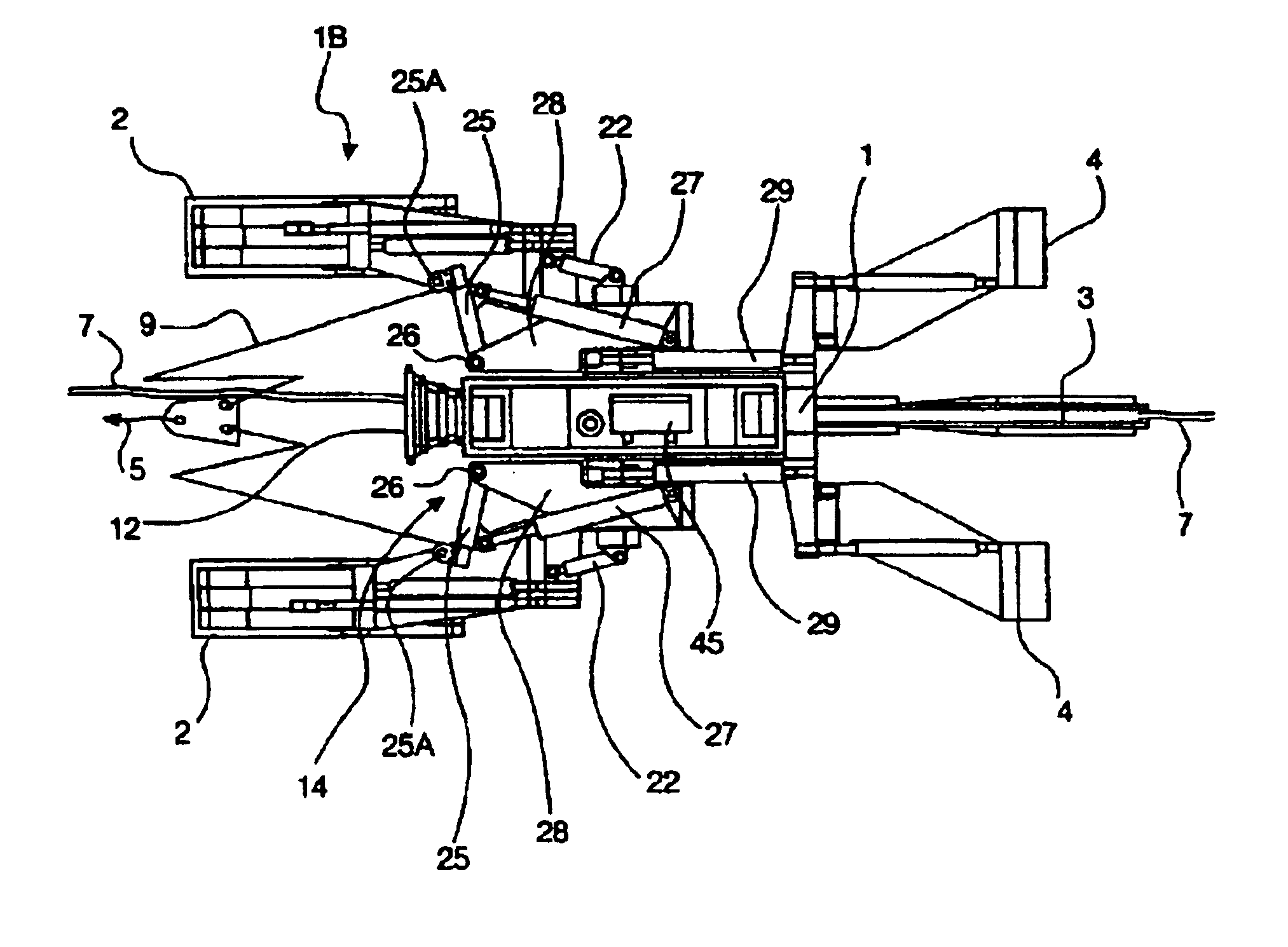
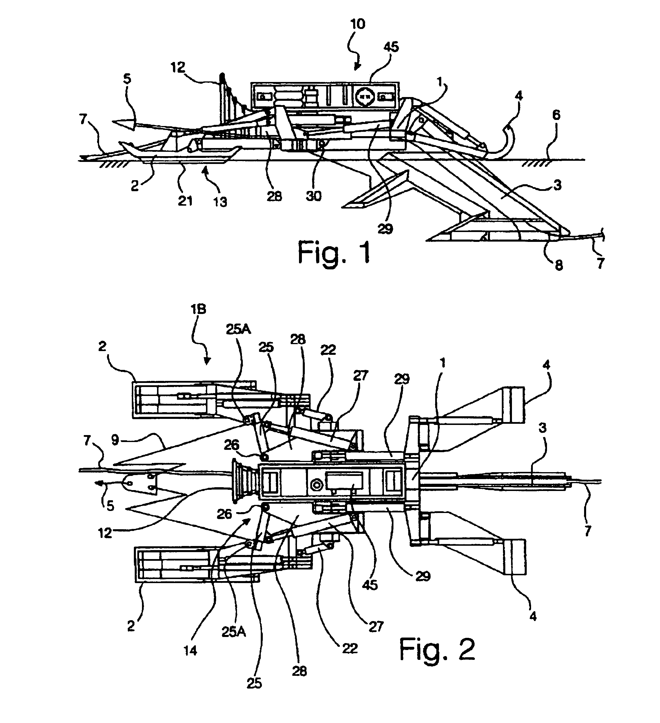
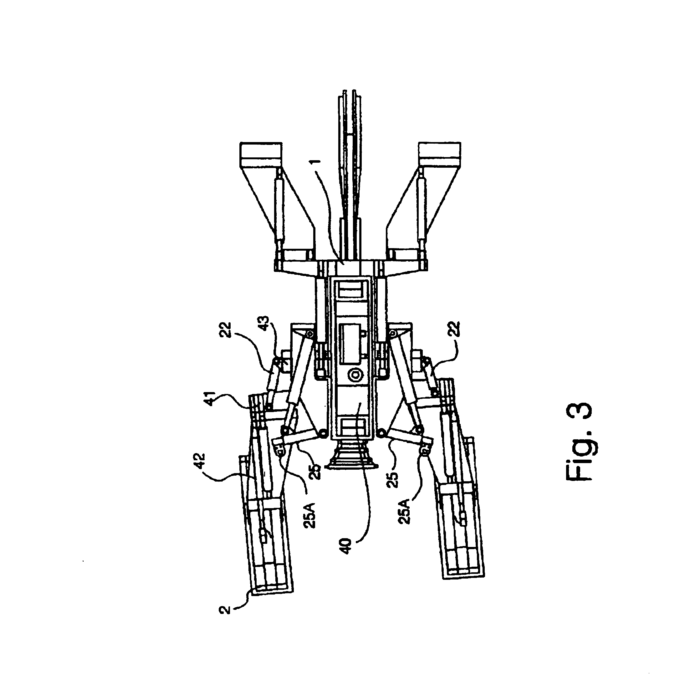
Referring to the FIGS. 1 to 5, a seabed cable plough is made up of an elongate chassis 1, a share 3 at the rear of plough 10, and support skids (2 and 4) two each at the front and rear respectively. The front skids 2 support the plough on the seabed 6 and are adjustable by hydraulic rams 42 in FIGS. 3 and 5) to set the trenching depth of the plough. The share 3 penetrates the seabed as the plough is towed by a ship (not shown) via a towrope 5. Cable 7 to be buried enters the front of the plough at bellmouth 12 and exits underground at the back of the plough 8. Rear spaced skids 4 support the back of the plough when operating in very soft seabed soils. The plough may be fitted with a control and monitoring system and a hydraulic power pack, typically located on top of the plough at 45, allowing the operators on the ship to operate it effectively by controlling the position of the hydraulic rams. Alternative adjustment mechanisms to rams can be used although rams are particularly suit...


PUM


Abstract

A marine plough includes twin, complementary steering mechanisms, one or more soil-engaging fins, which are able to be steered, and a tow rope attachment mechanism that enables adjustment of the position of the tow rope retention point relative to the plough. This alters the position at which the line of a tow rope crosses the longitudinal axis of the plough, so that the plough can operate at offset tow positions. The tow rope attachment mechanism includes a bridle having two bridle limbs terminating at respective bridle limb retention points. The adjustment of the position of the tow rope retention point relative to the plough is done by moving the bridle rope retention points or adjusting the relative length of the bridle limbs. The bridle limb retention points can be moved, using cylinders, from towing positions to lifting positions at which the tow bridle can be used to lift plough in a substantially level attitude. The soil-engaging fins are carried by supporting skids, in turn carried by a steering member able to be pivoted relative to the plough about a substantially vertical axis. Ploughing depth can be adjusted by altering the vertical distance between the skids and the steering member.

Description

BACKGROUND TO THE INVENTIONThis invention relates to ploughs, particularly those for burial of cables and pipelines in the bed of the sea or other water. Ploughs are well-known for use in protecting cable and pipelines underwater. The cables or pipelines are buried to protect them from damage by, for example, fishing equipment or anchors. Typically these ploughs are towed via a towrope by a vessel on the surface of the water, but may be towed by an underwater tractor. Such ploughs are fitted with a soil-engaging share that is shaped to dig into the seabed under the action of the towing force and produce a trench into which the cable or pipe is placed. The ploughs usually lay the cable or pipeline in the trench. The invention applies to all types of plough.Hitherto, such ploughs have often been fitted with a steering system that operates by exerting transverse forces on the tow wire and thus generating couples on the plough that alter the direction of travel of the plough. Some of th...

Claims


Application Information

Patent Timeline
IPC IPC(8): E02F5/14E02F5/02E02F5/10H02G1/10
CPCE02F5/102E02F5/104H02G1/10E02F5/145E02F5/106
Inventor GRINSTED, TIMOTHY WILLIAM
Owner IHC ENGINEERING BUSINESS LIMITED
Learn More