
Snow plowing system

a technology of snow plows and snow plows, applied in the field of excavating, can solve the problems of heart attack, stroke, death, inability to fit plows into larger areas or deeper snow, and reducing the chance of physical, stroke, stroke, and death in those with compromised cardiovascular systems. the effect of reducing the possibility of damage and reducing the surface damag

Active Publication Date: 2009-09-08
DEGELMAN IND LP
View PDF32 Cites 31 Cited by
  • Summary
  • Abstract
  • Description
  • Claims
  • Application Information

AI Technical Summary

Benefits of technology

[0015]In a third manifestation, the invention is a snow plow. The snow plow has a main blade, with first and second wings flanking and pivotally coupled to the main blade at first and second main blade-to-wing pivots, respectively. A first power cylinder is coupled to the first wing at a first wing-to-cylinder pivot and coupled to the main blade at a first main blade-to-cylinder pivot. The first power cylinder is retractable to be shorter than a combined minimum distance between the first main blade-to-cylinder pivot and first wing-to-cylinder pivot and extendable to be longer than a maximum distance between first main blade-to-cylinder pivot and first wing-to-cylinder pivot summed with a maximum distance between the first main blade-to-cylinder pivot and the first main blade-to-wing pivot.OBJECTS OF THE INVENTION
[0017]A first object of the invention is to only require nominal finished weight, while still being structurally engineered for strength and durability. A second object of the invention is to provide plows in different heights and widths, including widths which may be either substantially greater than the width of a traffic lane, such as, for exemplary purpose, 16, 18 and 20 foot widths, or narrower, as may be desired. Another object of the present invention is to enable the snow plowing system which achieves the foregoing objects to be easily loaded on a standard skid-steer trailer, without detachment from the skid steer and which may be transported through spaces of approximately the size of standard motive vehicles and within a single standard traffic lane. A further object of the invention is to provide snow plowing blades that are fully functional no matter what relative position they are in, thereby enabling the functions provided by a prior art box plow / pusher, conventional plow, pull back / drag, V-plow and a fold-out. Yet another object of the present invention is to enable plow wings, when in the most forward position, to glide effortlessly over sidewalks and curbs, minimizing both surface damage and the possibility of damage to the motive machine or the present inventive snow plowing system.

Problems solved by technology

Plows also reduce the chance of physical over-exertion, which can lead to heart attacks, strokes and death in those with compromised cardiovascular systems.
In the case of the ATV, clearing a light snow in a relatively small space is quite feasible, but such plows are just not suitable for either larger areas or deeper snows.
The ATV is not heavy enough nor powerful enough to move substantial snow.
Consequently, the vast majority of plows are limited to clearing an approximately eight foot wide pathway.
Furthermore, and as aforementioned, these plows are unable to pile the snow beyond a height limited by the height of the blade and weight and traction of the vehicle.
However, road graders are very specialized and expensive machines, the price which is beyond most individuals and organizations that are involved in snow clearing and removal.
Consequently, it is impossible to accumulate snow at any elevation much higher than the blade.

Method used


Image

  • Snow plowing system
  • Snow plowing system
  • Snow plowing system

Examples


Embodiment Construction

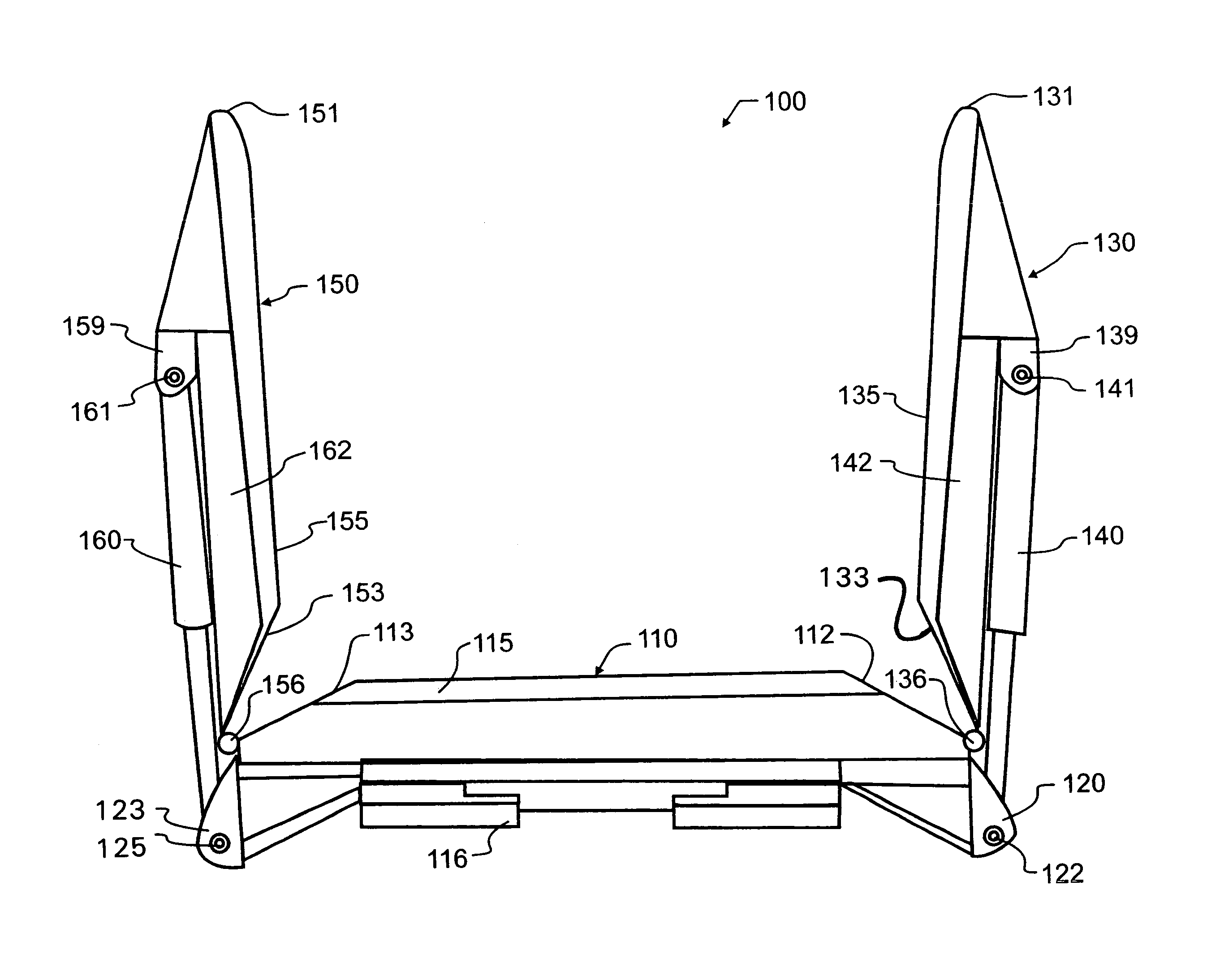
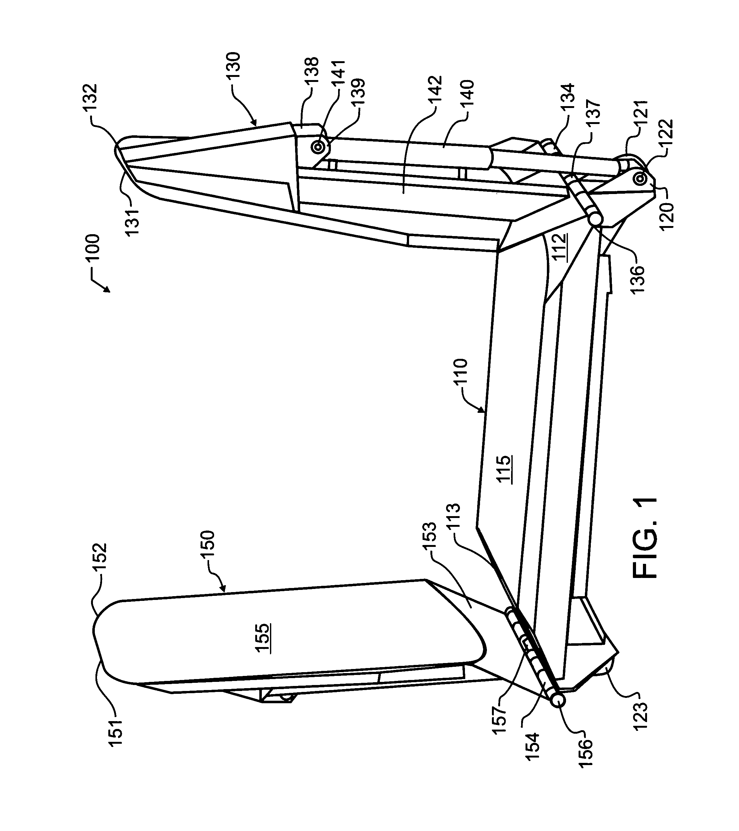
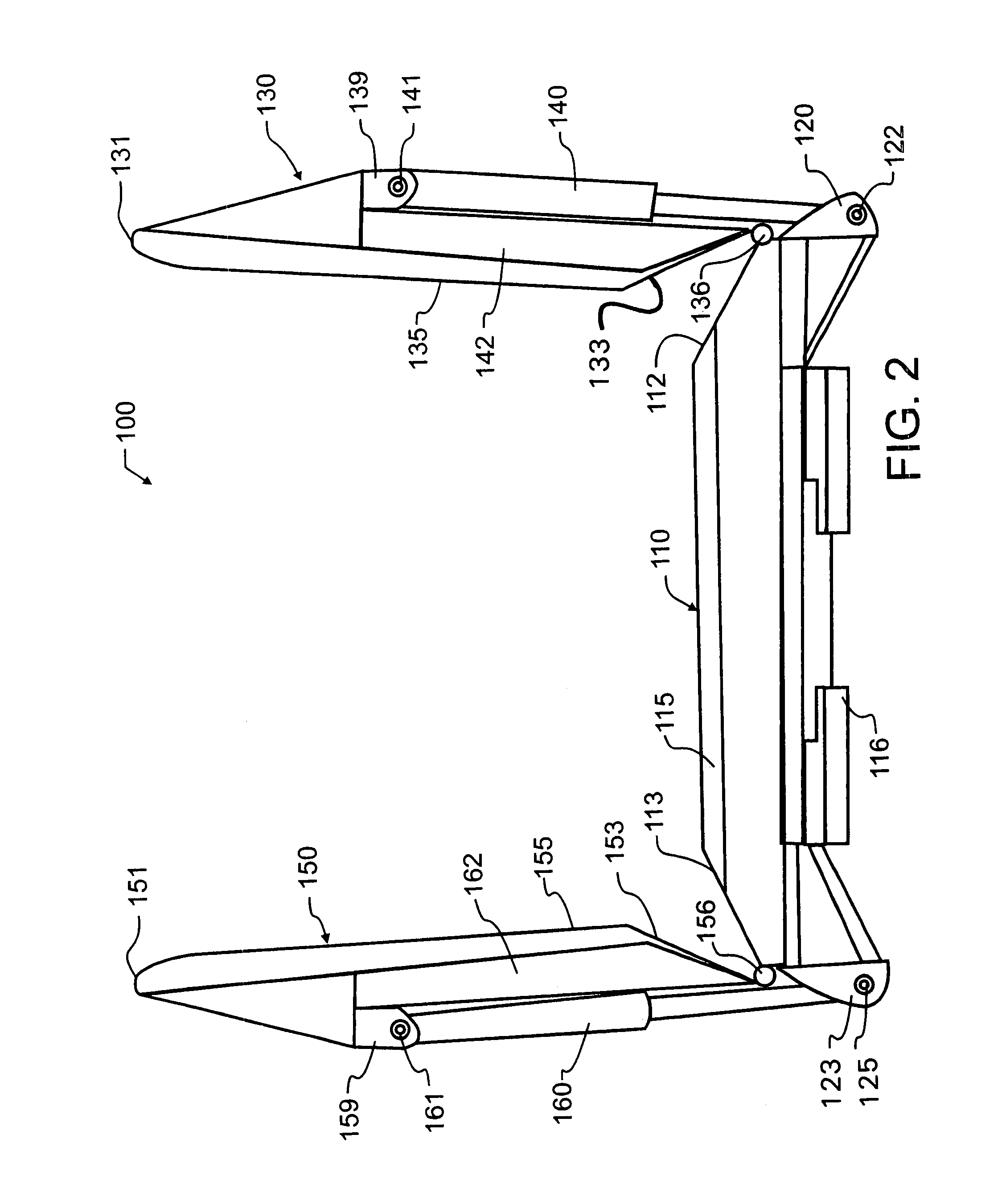
[0029]Manifested in the preferred embodiment, the present invention provides a snow plowing system 100 which comprises three main sections. A main blade 110 is flanked on opposite ends by right wing 130 and left wing 150. FIGS. 1-3 illustrate preferred embodiment snow plowing system 100 having right and left wings 130, 150 extending generally perpendicularly from and leading centrally located main blade 110. For the purposes of the present disclosure, the words leading and trailing will be understood to be assumed for a direction of typical forward travel by a vehicle coupled as shown for exemplary purposes in FIG. 10, wherein such a vehicle would normally travel in a forward direction from the back side of main blade 110, adjacent coupling 116, and will be urging against coupling 116 towards surface 115. Nevertheless, one of the features and benefits of the preferred embodiment is the ability to push or pull. Consequently, the words leading and trailing are simply for the purposes ...


PUM


Abstract

A detachable snow plow blade is driven by a skid-steer or other suitable vehicle. The detachable plow blade has hydraulically adjustable wing blades that each pivot under separate control about a main blade. Pins that support power cylinders between braces are arranged to enable each wing to extend through a range of motion from essentially perpendicular to and ahead of the main blade to essentially perpendicular to and behind the main blade. In a further alternative embodiment, the entire blade, including wing blades, may additionally be pivoted with respect to the vehicle, resulting in a very adjustable blade which is well adapted to emulate prior art box plow / pushers, conventional plows, pull back / drag plows, V-plows and fold-out plows.

Description

CROSS REFERENCE TO RELATED APPLICATIONS[0001]This application claims priority to U.S. provisional patent application Ser. No. 60 / 578,793 filed Jun. 9, 2004 by the present inventor and entitled “Snovantage Snow Plowing System,” the contents which are incorporated herein by reference in entirety.BACKGROUND OF THE INVENTION[0002]1. Field of the Invention[0003]This application pertains generally to the field of excavating, and more particularly to snow or ice removal using scraper blades with auxiliary wings or extensions. In one preferred embodiment, the invention is a snow plow blade having a central section, the central section leading and coupled to a skid-steer, and two pivotal wings extending beyond the skid-steer and central section, both wings which are each separately adjustable through a nearly one hundred and eighty degree arc.[0004]2. Description of the Related Art[0005]Most modern transportation is based upon wheels, which perform much better traveling over clear, dry roadw...

Claims


Application Information

Patent Timeline
IPC IPC(8): E01H5/06
CPCE01H5/065
Inventor NISTLER, TIMOTHY A.
Owner DEGELMAN IND LP
Learn More