Punching-shear composite drill bit for hard rock drilling

A composite drill bit, punching and shearing technology, applied in the direction of drill bit, drilling equipment, earthwork drilling and production, etc., can solve the problems that affect the application of percussion rotary drilling technology, high energy consumption, limited service life, etc., to reduce the stick-slip phenomenon of the drill bit, Improve the efficiency of rock breaking and strengthen the effect of self-protection

Active Publication Date: 2018-03-27
XIAN RES INST OF CHINA COAL TECH& ENG GROUP CORP
View PDF6 Cites 29 Cited by
  • Summary
  • Abstract
  • Description
  • Claims
  • Application Information

AI Technical Summary

Problems solved by technology

When drilling, the drill bit is not only under the action of a certain axial pressure, but also driven by the drilling rig to rotate through the drill string, and at the same time bears a certain frequency of impact energy, while the impact toughness of the cutting teeth of the PDC bit is relatively limited. The cutting teeth are prone to chipping under the action of the impact rotary drilling process. Therefore, the DTH hammer drill bit used in the impact rotary drilling process is generally made of cemented carbide, and the wear resistance of cemented carbide is relatively poor, especially when the diameter of the drill is small. When it is large, the outer ring carbide teeth wear faster, resulting in limited service life
In addition, when the hole diameter is large, the large-diameter down-the-hole hammer used is powered by wind, and the drilling efficiency increases with the increase of air supply volume. At the same time, the required air volume for slag removal is also large, so it must be equipped with a multi-hole hammer with sufficient air supply volume. A single air compressor requires a large investment and high energy consumption, which directly affects the application of percussion rotary drilling technology

Method used


Image

  • Punching-shear composite drill bit for hard rock drilling
  • Punching-shear composite drill bit for hard rock drilling
  • Punching-shear composite drill bit for hard rock drilling

Examples


Embodiment Construction

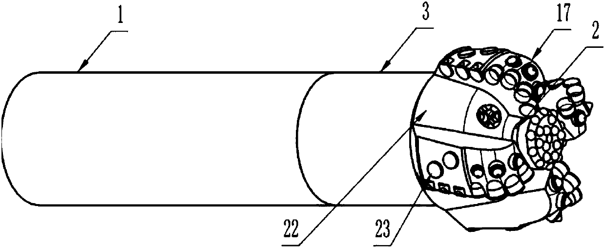
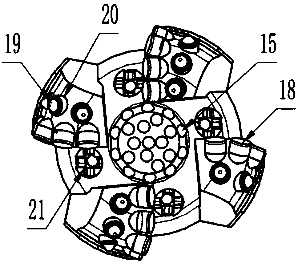
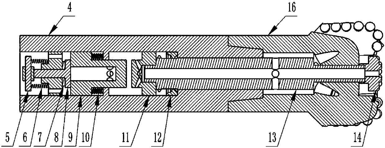
[0026] see Figure 1 to Figure 4 , shows the punching-shear composite drill bit for drilling hard rock of the present invention.

[0027] Such as figure 1 and Figure 1A As shown, the punching and shearing composite drill bit for hard rock drilling can include three parts: an impactor 1, an inner punching drill bit 2 and an outer cutting bit 3, and the lower joint of the impactor 1 and the outer cutting bit 3 can be threaded. Form connection, the upper part of the inner punching drill bit 2 is connected with the impactor 1 through a spline, the lower end surface of the inner filling drill bit 2 protrudes from the surface of the outer cutting drill bit 3 and is located on the outer cutting drill bit 3, the inner punching drill bit 2 The central axis of the drill bit 2 is parallel or coincident with the central axis of the circumscribed drill bit 3, and the combination of the set teeth on the inner filled drill bit 2 and the set teeth of the circumscribed drill bit 3 can compl...


PUM


Abstract

The invention discloses a punching-shear composite drill bit for hard rock drilling. The punching-shear composite drill bit comprises three parts of an impactor, an internal punching bore bit and an external cutting drill bit, a lower joint of the impactor can be in threaded connection with the external cutting drill bit, and the upper part of the internal punching bore bit is connected with the impactor in a spline mode; and the lower end face of the internal punching bore bit extends out of the surface of the external cutting drill bit, the central axis of the internal punching bore bit is parallel to or coincident with the central axis of the external cutting drill bit, distributed teeth on the internal punching bore bit and distributed teeth on the external cutting drill bit are combined and can completely cover a downhole, and distributed teeth on the internal punching bore bit and the distributed teeth on the external cutting drill bit are independent of each other. In this way,rock crushing through shearing and rock crushing through impact are creatively combined together, a rock stratum at the hole bottom is pre-cracked first through the internal punching bore bit, the whole tectonic stress of the rock stratum is destroyed, the strength of compression resistance and shearing resistance of rock is reduced so that PDC column teeth and PDC cone teeth can more easily cut / plough-cut the rock, and the rock-breaking efficiency of the super hard rock stratum is greatly improved.

Description

technical field [0001] The invention relates to the technical field of drilling tools for exploration and development of petroleum gas, coal bed methane, etc., in particular to a punching-shear composite drill bit for hard rock drilling. Background technique [0002] The PDC bit breaks the rock through the compressive shearing effect of the cutting teeth on the rock in front of the blade, and makes full use of the low shear strength of the rock. The proportion of drilling in soft to medium hard formations is far higher than that of the roller cone bit. An important way to save drilling costs. However, as the demand for exploration and development of oil and gas and coalbed methane becomes stronger, more and more deep wells and ultra-deep wells are drilled, and the formation conditions encountered are becoming more and more complicated. Quartz sandstone, conglomerate, and chert are often drilled. For formations with high hardness, strong abrasiveness, and poor drillability, ...

Claims


Application Information

Patent Timeline
Patent Type & Authority Applications(China)
IPC IPC(8): E21B10/46E21B10/62
CPCE21B10/46E21B10/62
Inventor 王传留居培田宏杰高晓亮李耿张朋温国栋
Owner XIAN RES INST OF CHINA COAL TECH& ENG GROUP CORP
Why Eureka
Try Eureka