Chemical mechanical polisher with grooved belt

a mechanical polisher and groove technology, applied in the direction of grinding machines, manufacturing tools, lapping machines, etc., can solve the problems of limited effectiveness of slurry distribution method, poor polishing effect of surface of polishing pad, and relatively complex process of cmp, so as to improve ensure uniform polishing. , the effect of improving the life of the pad

Inactive Publication Date: 2005-01-04
APPLIED MATERIALS INC
View PDF26 Cites 28 Cited by
  • Summary
  • Abstract
  • Description
  • Claims
  • Application Information

AI Technical Summary

Benefits of technology

Advantages of the invention may include the following. The grooves of the polishing pad provide an effective way to distribute slurry across the pad. Slurry may be distributed to the substrate more uniformly, thereby providing more uniform polishing across the substrate. The grooves are sufficiently wide that waste material produced by a conditioning process can be flushed from the grooves. The relatively deep grooves also improve the pad lifetime.

Problems solved by technology

One problem in CMP relates to slurry distribution.
The CMP process is fairly complex, requiring the interaction of the polishing pad, abrasive particles and reactive agent with the substrate.
Accordingly, ineffective distribution of the slurry across the surface of the polishing pad provide less than optimal polishing results.
This method of slurry distribution has limited effectiveness because each perforation in effect acts independently.
Thus, some of the perforations may have too little slurry, while others may have too much slurry.
Furthermore, there is no way to directly channel the excess slurry to where it is needed.
Another problem in CMP is “glazing” of the conventional (non-fixed abrasive) rotatable polishing pad.
As a result, the polishing time required to polish a substrate increases.
In addition, during the conditioning process, waste materials associated with abrading the surface of the pad may fill or clog the perforations in the polishing pad.
Filled or clogged perforations can not hold slurry, thereby reducing the effectiveness of the polishing process.

Method used


Image

  • Chemical mechanical polisher with grooved belt
  • Chemical mechanical polisher with grooved belt
  • Chemical mechanical polisher with grooved belt

Examples


Embodiment Construction

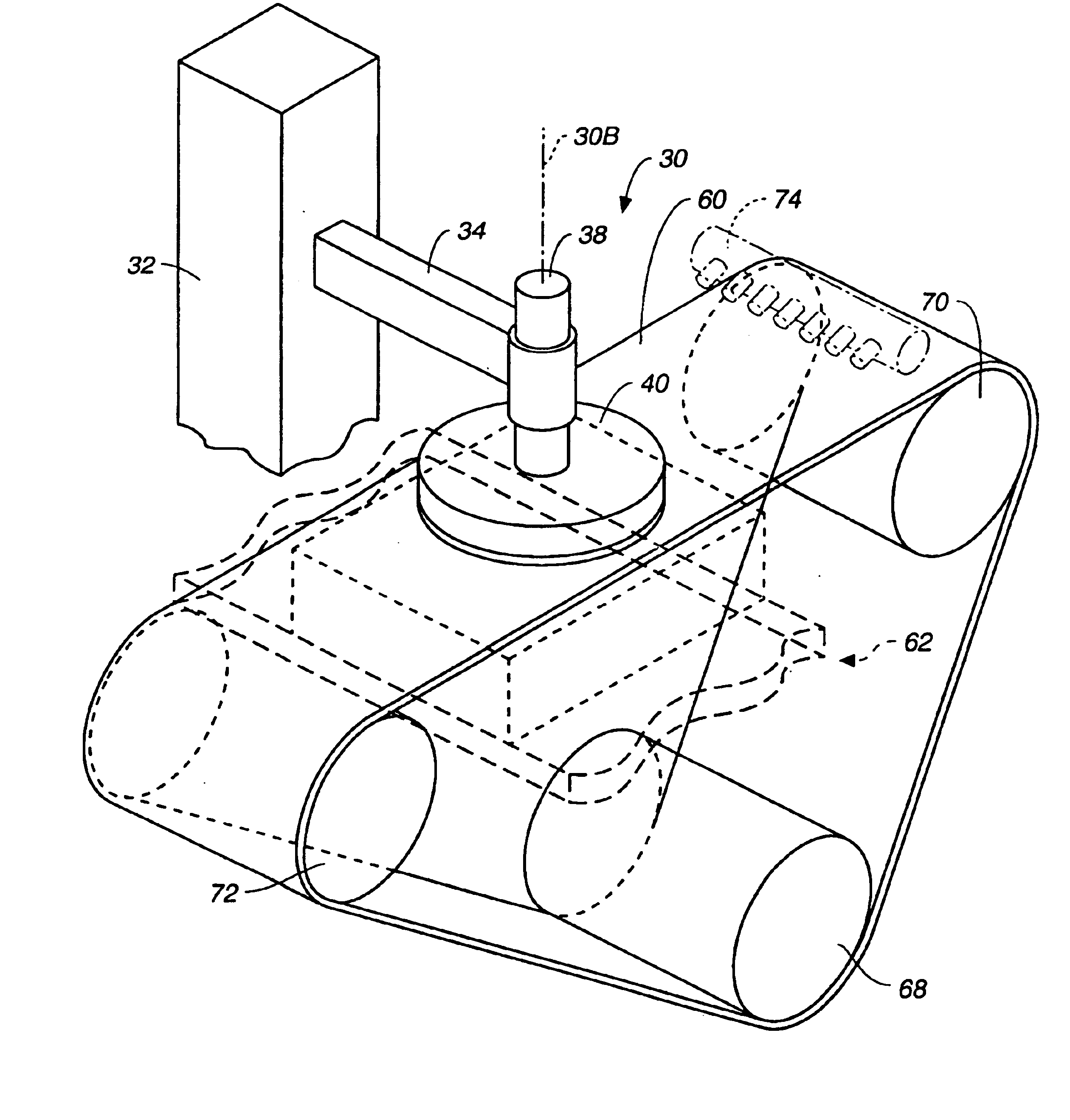
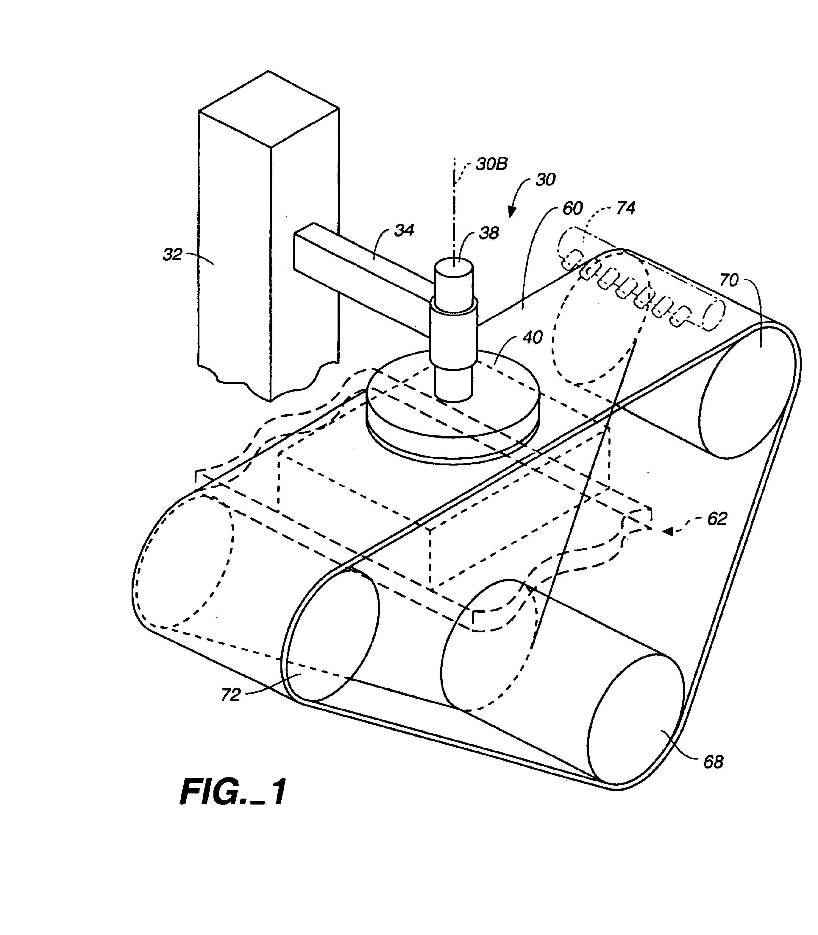
An apparatus of chemical mechanical polishing (CMP) is illustrated in FIG. 1. In this apparatus, a substrate surface is polished by using an abrasive slurry with an active chemical (e.g., an alkaline solution) in combination with a moving polishing belt 60.

A substrate (wafer) holder (polishing head) assembly 30 includes a fixed base 32 connected to a movable support arm or frame 34. The support frame 34 holds a polishing head shaft 38 which supports a polishing head 40. The polishing head shaft 38 can be rotated by a rotation mechanism (not shown) to control the rotation of the polishing head 40. The vertical position of the wafer holding surface of the polishing head 40 can be controlled, e.g., by a pressure chamber in the polishing head 40 or by a vertical actuator coupled to the polishing head shaft 38.

The polishing belt 60 is routed around three rollers 68, 70 and 72. During polishing, the belt moves continuously in a longitudinal direction between the top two rollers, e.g. from...


PUM

PropertyMeasurementUnit
depthaaaaaaaaaa
depthaaaaaaaaaa
depthaaaaaaaaaa

Abstract

A chemical mechanical polishing apparatus has a substrate holder, a polishing belt, and a backing member positioned on a side of the polishing belt opposite the substrate holder. The polishing belt has a polishing surface to contact at least a portion of the substrate held by the substrate holder. The polishing belt is movable in a first direction in a generally linear path relative to the substrate. The polishing belt has a plurality of grooves formed therein.

Description

BACKGROUNDThe present invention relates to chemical mechanical polishing. More particularly, the present invention relates to apparatus and methods for chemical mechanical polishing of substrates using a belt.Integrated circuits are typically formed on substrates, particularly silicon wafers, by the sequential deposition of conductive, semiconductive or insulative layers. After each layer is deposited, the layer is etched to create circuitry features. As a series of layers are sequentially deposited and etched, the outer or uppermost surface of the substrate, i.e., the exposed surface of the substrate, becomes increasingly non-planar.Chemical mechanical polishing (CMP) is one accepted method of planarizing a substrate. This method typically requires that the substrate be mounted on a carrier head. The exposed surface of the substrate is placed against a rotating polishing pad or moving polishing belt. The carrier head provides a controllable load, i.e., pressure, on the substrate to...

Claims


Application Information

Patent Timeline
Patent Type & Authority Patents(United States)
IPC IPC(8): B24B21/04B24B37/04B24D11/00B24B37/26
CPCB24B37/26B24B21/04
Inventor SMITH, CHRISTOPHER W.WHITE, JOHN M.
Owner APPLIED MATERIALS INC
Why Eureka
Try Eureka