UV toner fusing

a technology of toner fusing and ultraviolet light, applied in the field of printing, to achieve the effect of enhancing gloss fusing, high temperature, and facilitating the acceptance of electric charges

Inactive Publication Date: 2005-01-04
HEWLETT PACKARD DEV CO LP
View PDF4 Cites 17 Cited by
  • Summary
  • Abstract
  • Description
  • Claims
  • Application Information

AI Technical Summary

Benefits of technology

According to one aspect of the present invention there is disclosed a method of fusing an image to a page, the method including the steps of transferring toner from a photoconductive drum of a laser printer to a page, and separately fusing the toner to the page by the application of UV light to the toner. This method may be accomplished by a conventional laser printing apparatus with the addition of a UV fusing station, however the conventional laser printing apparatus may not include a heating element.
According to another aspect of the invention there is disclosed a borosilicate cylinder comprising a UV light source therein. The borosilicate roller may further include a UV translucent, compliant elastomer coating d

Problems solved by technology

This method may be accomplished by a conventional laser printing apparatus with the addition of a UV

Method used


Image

  • UV toner fusing
  • UV toner fusing
  • UV toner fusing

Examples


Embodiment Construction

Illustrative embodiments of the invention are described below. In the interest of clarity, not all features of an actual implementation are described in this specification. It will of course be appreciated that in the development of any such actual embodiment, numerous implementation-specific decisions must be made to achieve the developers' specific goals, such as compliance with system-related and business-related constraints, that will vary from one implementation to another. Moreover, it will be appreciated that such a development effort might be complex and time-consuming, but would nevertheless be a routine undertaking for those of ordinary skill in the art having the benefit of this disclosure.

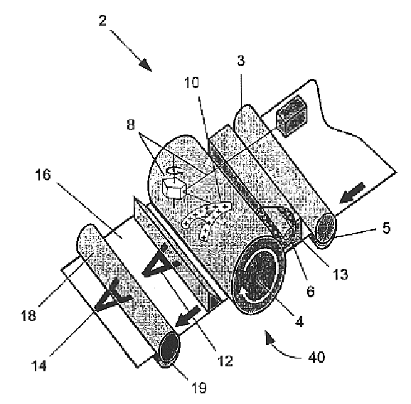
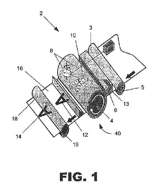
Turning now to the drawings, and in particular to FIG. 1, one embodiment of a laser printing apparatus (2) according to the present invention is shown. Laser printing apparatus (2) may include one or more photosensitive drums, for example organic photoconductive drum (4). Photoconductiv...


PUM


Abstract

A method and apparatus for fusing toner to a laser printed page. The apparatus includes a photosensitive drum, a laser optic system for tracing an image on the photosensitive drum, a toner supply electrically charged opposite the image traced on the photosensitive drum, and an ultraviolet light source for imparting energy to the toner to fuse the toner to the page. The apparatus facilitates faster print speeds and lower energy consumption than conventional laser printers that require heating elements to fuse the toner to the page.

Description

FIELDThe present invention relates to printing, and more particularly to the process of fusing toner to paper.BACKGROUNDModem laser printing is generally accomplished by what is commonly known as the electrophotographic process. At the heart of the imaging process is an organic photoconductive (OPC) drum, and the drum typically includes an extruded aluminum cylinder coated with a non-toxic organic photoconductive material. There are six generalized stages to the electrophotography process: cleaning, conditioning, writing, developing, transferring and fixing.Cleaning is the first stage in the imaging process. This stage prepares the OPC drum to receive a new latent image by applying a physical and electrical cleaning process. The physical cleaning of the OPC is typically accomplished by a drum-cleaning blade (or wiper blade) and a recovery blade. The wiper blade scrapes any excess toner from the drum and the recovery blade catches the toner and sweeps it into a waste hopper. In the e...

Claims


Application Information

Patent Timeline
IPC IPC(8): G03G15/20
CPCG03G15/2007G03G15/2098
Inventor PAYNE, DAVID M.PAYNE, RICHARD L.
Owner HEWLETT PACKARD DEV CO LP
Why Eureka
Try Eureka