Separation microcolumn assembly for a microgas chromatograph and the like

a technology of microgas chromatograph and assembly, which is applied in the direction of ohmic resistance heating, separation processes, instruments, etc., can solve the problems of large size, fragile, and relatively expensive table-top instruments of conventional gc systems, and achieve the effect of improving the separation of microcolumn assemblies

Inactive Publication Date: 2005-01-04
RGT UNIV OF MICHIGAN
View PDF26 Cites 74 Cited by
  • Summary
  • Abstract
  • Description
  • Claims
  • Application Information

AI Technical Summary

Benefits of technology

An object of the present invention is to provide improved separation microcolumn assemblies for a microgas chromatograph and the like.

Problems solved by technology

Conventional GC systems tend to be large, fragile, and relatively expensive table-top instruments.

Method used


Image

  • Separation microcolumn assembly for a microgas chromatograph and the like
  • Separation microcolumn assembly for a microgas chromatograph and the like
  • Separation microcolumn assembly for a microgas chromatograph and the like

Examples


Embodiment Construction

As described hereinbelow, a number of innovative approaches to column miniaturization are introduced that significantly improve the operation of microGCs and indeed make the concept of a “μGC sensor” realistic.

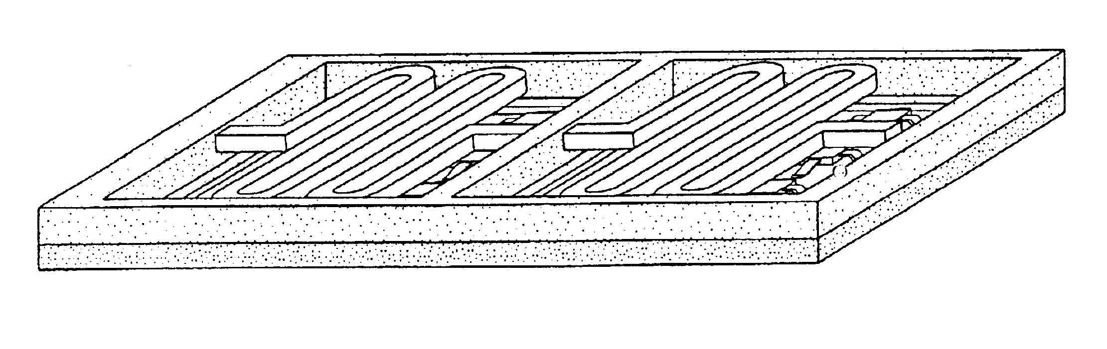
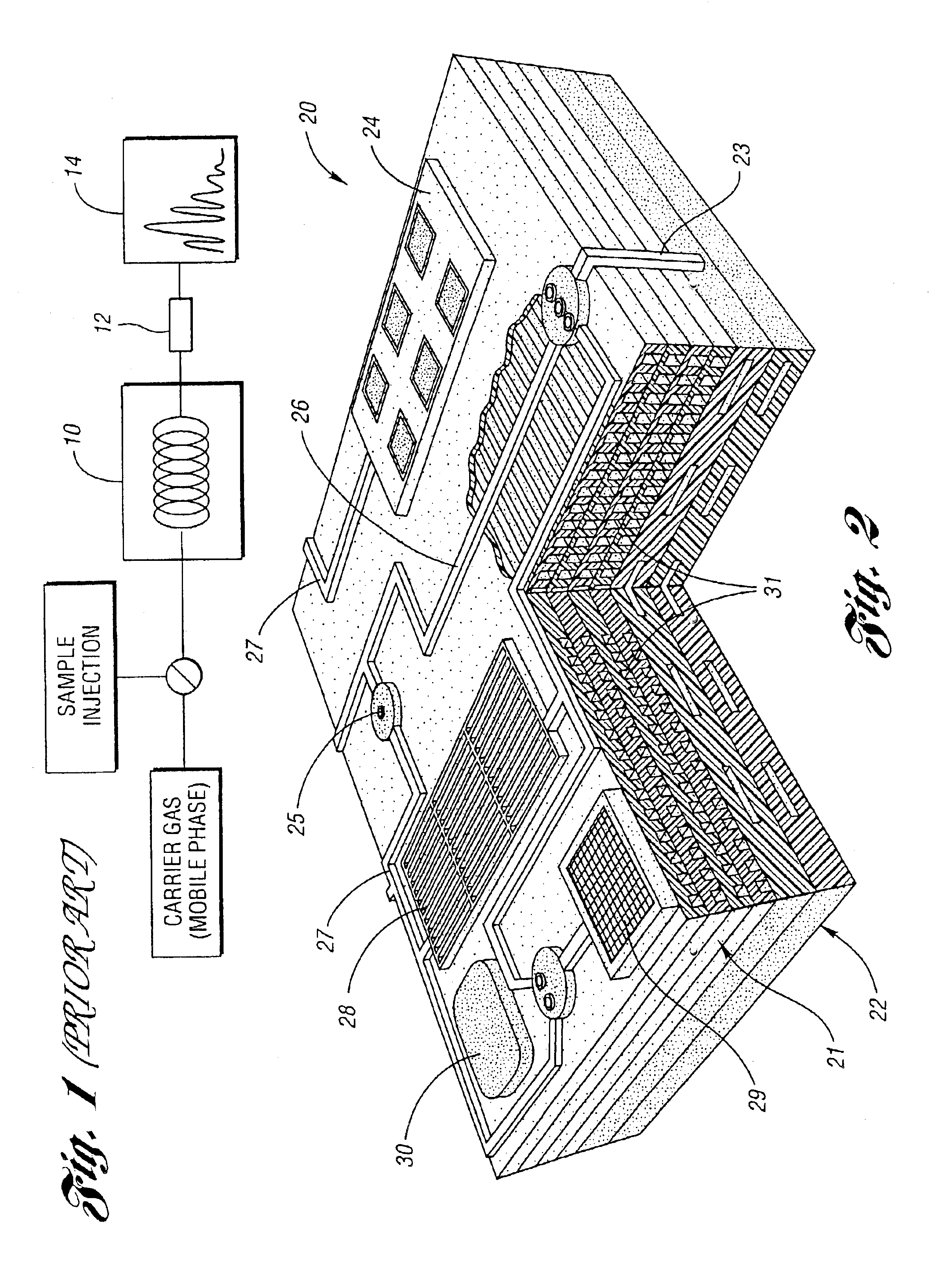
A microgas chromatograph utilizing a micromachined separation microcolumn assembly of the present invention is generally indicated at 20 in FIG. 2. The assembly is generally indicated at 21 and is in the form of a stacked DRIE microcolumn.

The chromatograph also includes a distributed vacuum pump 22 having pump vias 23, a multi-sensor array 24, a latching bypass valve 25, sealed channel 26, column vias 27, a multi-stage pre-concentrator 28, a filtered inlet 29 and a calibration source 30. The assembly 21 also includes polar / non-polar columns 31.

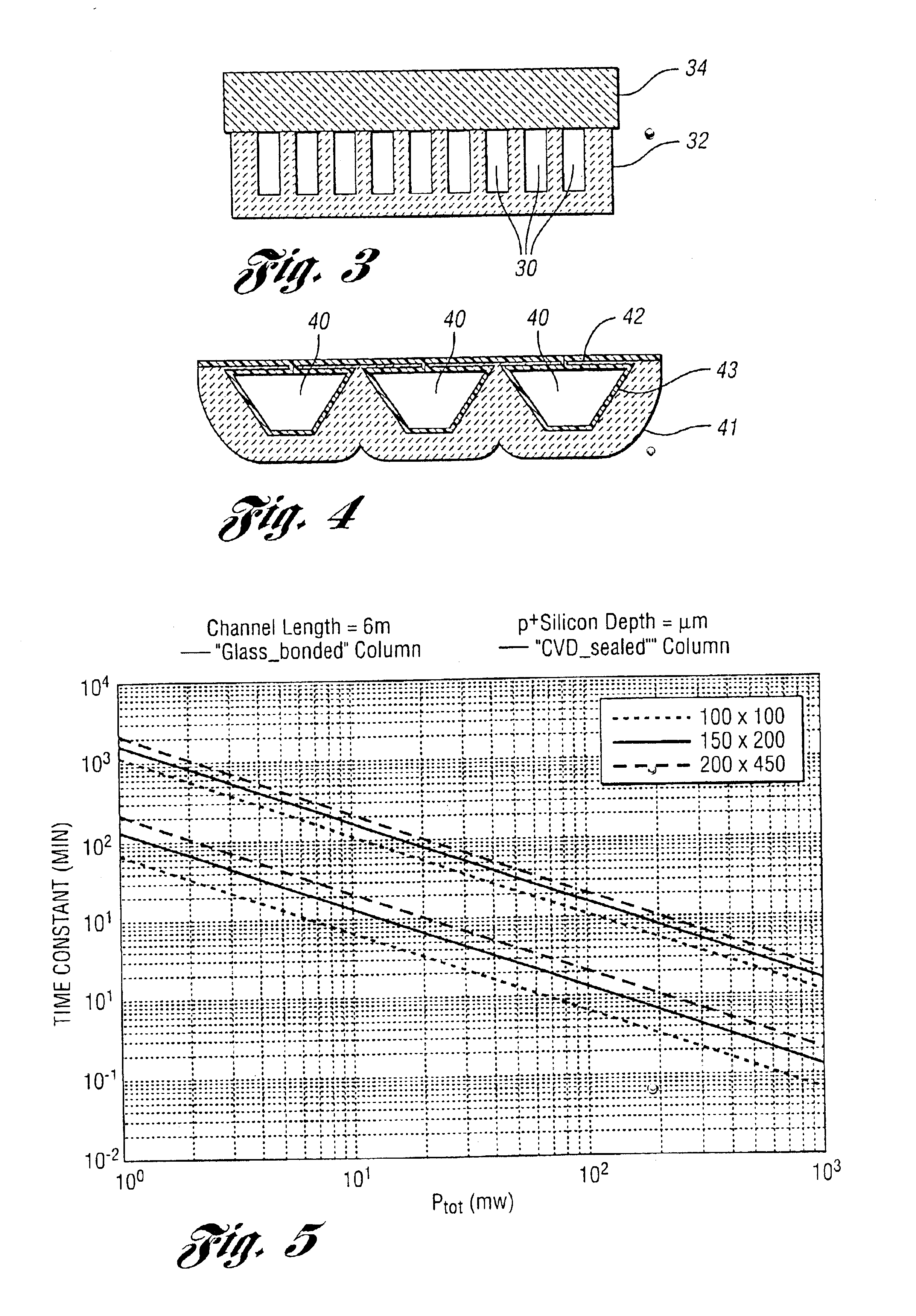
Some of the proposed approaches are not only applicable to gas chromatography systems but also can be applied to other applications that require multi-zone temperature control and rapid temperature changes. It is noted in a GC, the colum...


PUM

PropertyMeasurementUnit
temperaturesaaaaaaaaaa
thicknessaaaaaaaaaa
temperatureaaaaaaaaaa

Abstract

A high-sensitivity, separation microcolumn assembly for a microgas chromatograph and the like is provided. The assembly has an ultra-low mass complete with integrated heaters. The assembly uses multiple zones for temperature control, and microstructures that permit very rapid heating and cooling of the microcolumn.

Description

BACKGROUND OF THE INVENTION1. Field of the InventionThis invention relates to separation microcolumn assemblies for microgas chromatographs and the like.2. Background ArtThere are numerous challenging issues associated with the realization of a fast microGC (μGC) utilized as a “fieldable analytical instrument.”“Fieldable analytical chemistry” is defined as “the practice of producing appropriate qualitative and / or quantitative information with analytical instruments that are operated at or near the sample collection location and which convert data to chemical information in a time frame that is consistent with near real-time application.”GC systems are chemical instruments by which the components of a gaseous mixture can be separated, identified, and the constituent concentrations qualified. FIG. 1 shows the schematic of a GC system in which a sample is vaporized and injected onto the head of the separation column 10, the heart of the system. The sample is transported through the col...

Claims


Application Information

Patent Timeline
Patent Type & Authority Patents(United States)
IPC IPC(8): G01N30/60G01N30/00G01N30/30G01N30/02
CPCG01N30/30G01N30/60G01N30/6095G01N2030/025G01N2030/6056G01N2030/8881G01N2030/3084
Inventor WISE, KENSALL D.SACKS, RICHARDBEACH, KATHARINE T.POTKAY, JOSEPH A.AGAH, MASOUD
Owner RGT UNIV OF MICHIGAN
Why Eureka
Try Eureka