Light spot position sensor and displacement measuring device

a technology of displacement measurement and position sensor, which is applied in the direction of converting sensor output optically, instruments, material analysis, etc., can solve the problems of increasing cost and affecting actual precision, and achieve the effect of reducing cos

Inactive Publication Date: 2005-01-04
MITUTOYO CORP
View PDF9 Cites 26 Cited by
  • Summary
  • Abstract
  • Description
  • Claims
  • Application Information

AI Technical Summary

Benefits of technology

The present invention has been made in consideration of the above disadvantages and accordingly has an object to provide a light spot position sensor with no restriction on size. In addition, the light spot position sensor is possible to have an arbitrary shape and photosensitive pixel size. Further, it can detect a light spot position precisely and reduce the cost.

Problems solved by technology

In addition, it elevates the cost and is affected from an actual precision.

Method used


Image

  • Light spot position sensor and displacement measuring device
  • Light spot position sensor and displacement measuring device
  • Light spot position sensor and displacement measuring device

Examples


Embodiment Construction

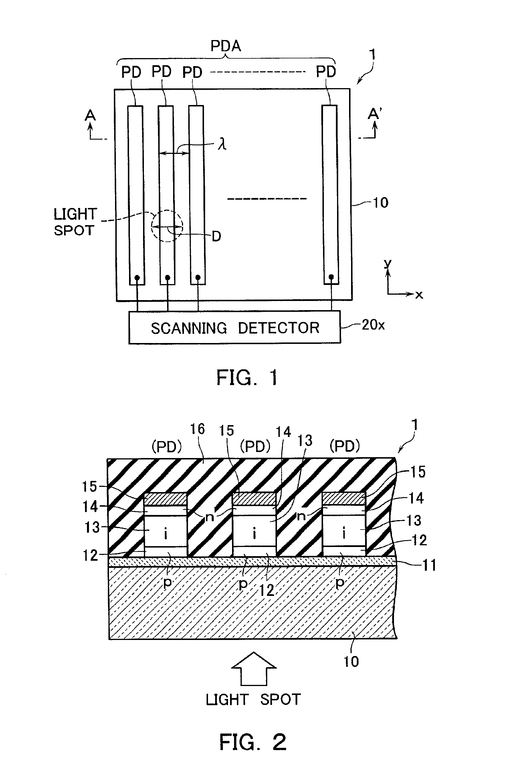
FIG. 1 is a plan view showing an arrangement of a one-dimensional light spot position sensor 1 for detecting a light spot position and FIG. 2 is a cross-sectional view thereof taken along an A-A′ line. The light spot position sensor 1 comprises a photosensitive device array PDA that includes photosensitive devices (photodiodes) PD shaped in stripes, arrayed along the x-axis and formed on a substrate 10.

The substrate 10 in this embodiment is a transparent substrate such as a glass substrate. A common lower electrode or transparent electrode 11 is formed on the substrate 10. On the transparent electrode 11, amorphous semiconductor layers of p-type 12, i-type 13 and n-type 14 and an upper electrode 15 are deposited in turn. These stacked layers are then patterned to isolate photodiodes PD from each other and array at a certain pitch. A passivation film 16 is formed to cover the photosensitive device array PDA.

The transparent electrode 11 is selected from ITO, SnO2, ZnO and the like. A ...


PUM

PropertyMeasurementUnit
time delayaaaaaaaaaa
angleaaaaaaaaaa
displacement measuringaaaaaaaaaa

Abstract

There is provided a displacement measuring device of which assembled state can be determined optically with ease. There is also provided a light spot position sensor usefully applicable in determination of the assembled state of the displacement measuring device. An optical encoder comprises a scale and a sensor head that is arranged opposite to the scale and can move relative to the scale. The sensor head includes a sensor substrate, on which an index grating and a photosensitive device array are formed. The sensor substrate is also employed to mount a light spot position sensor and a light source for providing a light beam entering the light spot position sensor via the scale to configure a state detection system for detecting an assembled state.

Description

BACKGROUND OF THE INVENTION1. Field of the InventionThe present invention relates to a sensor for detecting a light spot position and to a displacement measuring device using the sensor.2. Description of the Related ArtA sensor for detecting an incident position of a light spot can be configured using an existing image sensor such a CCD. Such a light spot position sensor is arranged on one of two members together with a light source for providing a light beam. The light beam output from the light source is reflected at the other of the two members and enters the light spot position sensor. It is theoretically possible to use an incident position of the light beam at this moment to detect a tilt or gap between the two members.There is no actual example of a displacement measuring device that incorporates the above existing CCD. When CCD is incorporated into an encoder part of a small displacement measuring device, a restriction on size causes several disadvantages. For example, the d...

Claims


Application Information

Patent Timeline
Patent Type & Authority Patents(United States)
IPC IPC(8): G01D5/26G01D5/347G01B11/03G01B11/24G01B11/00G01B11/245G01B11/30G01B21/20G01B21/30G01D5/30
CPCG01D5/34715G01D5/26
Inventor AOKI, TOSHIHIKO
Owner MITUTOYO CORP
Why Eureka
Try Eureka