Stall protection based on back EMF detection

a back emf detection and protection technology, applied in the direction of motor/generator/converter stopper, motor control, dynamo-electric converter, etc., can solve problems such as electric damage or even fire from overheating of the motor

Inactive Publication Date: 2005-01-04
BROSE FAHRZEUGTEILE GMBH & CO KG HALLSTADT (DE)
View PDF14 Cites 22 Cited by
  • Summary
  • Abstract
  • Description
  • Claims
  • Application Information

AI Technical Summary

Benefits of technology

An object of the invention is to fulfill the need referred to above. In accordance with the principles of the present invention, this objective is achieved by providing a motor control circuit for detecting a condition for a rotor of a dc motor. The motor control circuit includes a dc motor having a rotor. A power supply supplies power to the motor. A free-wheeling diode is in parallel with the motor. A switch is provided to cut-off current to the motor. At least one diode is connected in series with a positive terminal of the motor to establish a voltage threshold. An open collector comparator is provided and a voltage tap is provided to detect voltage across leads of the motor. A controller is constructed and arranged to control operation of the switch such that when the switch is turned off, cutting-off current to the motor, back emf voltage can be detected via the voltage tap and be compared via the comparator to the threshold voltage.
In accordance with another

Problems solved by technology

Without stall protection, it is possible for electrical d

Method used


Image

  • Stall protection based on back EMF detection
  • Stall protection based on back EMF detection
  • Stall protection based on back EMF detection

Examples


Embodiment Construction

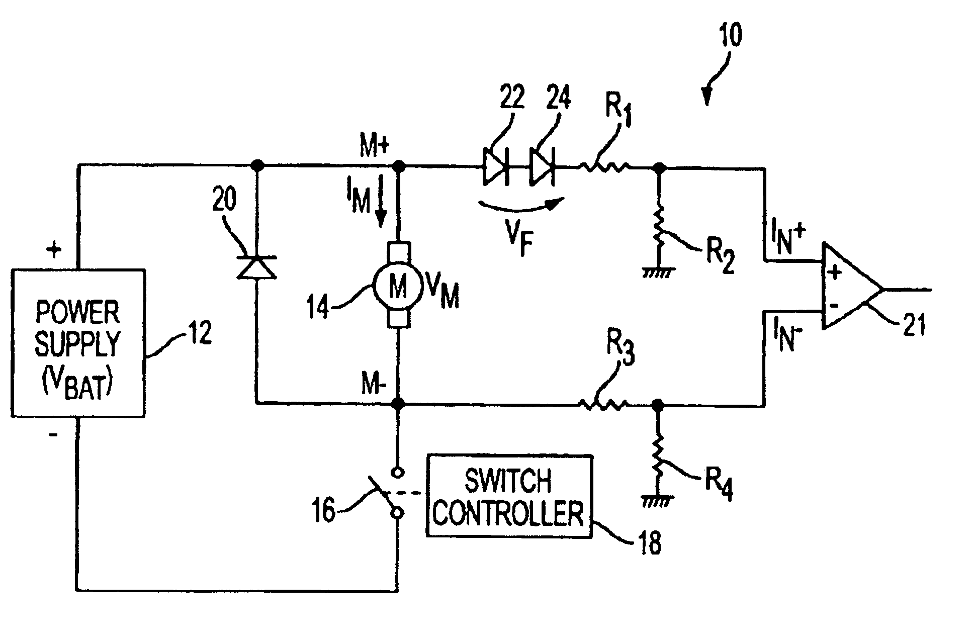
With reference to FIG. 1, an exemplary embodiment of a motor control circuit with back emf detection is shown, generally indicated at 10, in accordance with the principles of the present invention. A power supply 12 provides power to a motor 14. The motor 14 is a conventional dc motor having a rotor (not shown). The control circuit is contemplated for use in an engine cooling module of a vehicle in the temperature range of −40 C to 110 C and operating in the range of 100-400 Hz. It can be appreciated that the control circuit 10 can be used to determining stall of any dc motor.

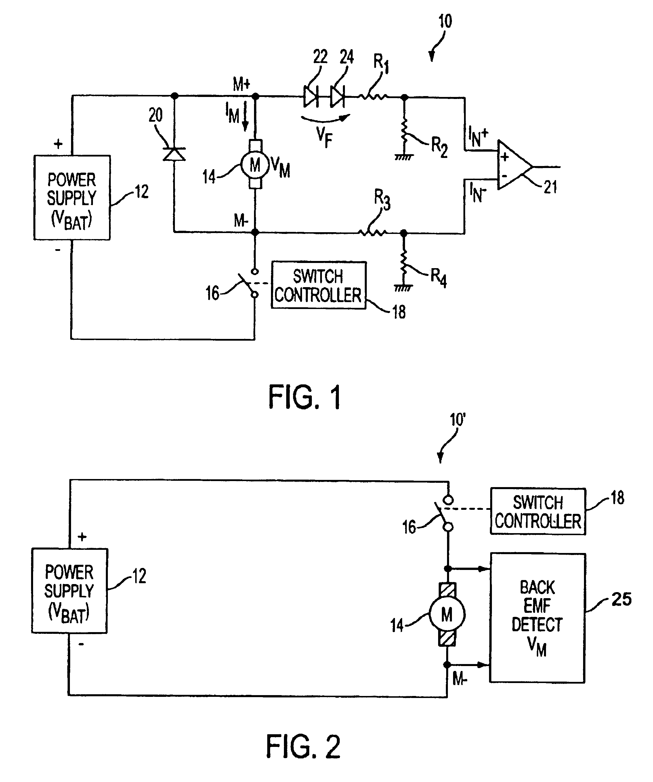
In FIG. 1, a switch 16 is in series with the power supply and the motor. In the embodiment of FIG. 1, the switch is connected to the negative lead of the motor. However, it can be appreciated that the switch 16 be connected to the positive lead of the motor as shown in the circuit 10 of FIG. 2.

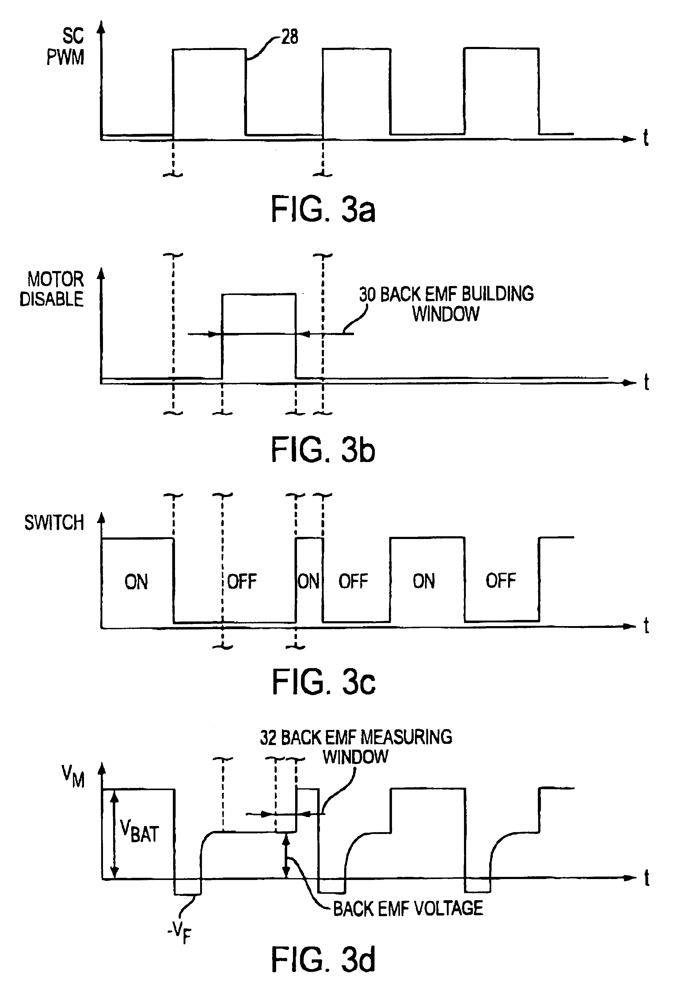
For pulse width modulation (PWM) control of the motor 14, the switch 16 is preferably a FET or MOSFET that is controlle...


PUM


Abstract

A method of detecting a rotor condition of a dc motor is provided. The motor 14 is part of a motor control circuit 10 having a free-wheeling diode 20 in parallel with the motor 14. The method establishes a threshold voltage for back emf voltage evaluation. The motor is energized to operate at a certain speed. Current is cut-off to the motor via a switch 16 for a time sufficient for current through the free-wheeling diode to decay to zero. The back emf voltage detected at leads of the motor is then compared via a comparator 21 to the threshold voltage.

Description

FIELD OF THE INVENTIONThe invention relates to detecting a blocked rotor condition of a dc motor and more particularly, detecting a blocked rotor condition at motor start up and during motor operation.BACKGROUND OF THE INVENTIONDirect current motors are commonly used in vehicle engine cooling systems to drive, for example, and engine cooling fan. In the event a dc motor is stalled, for example if some foreign object is blocking the fan wheel or the motor, some form of blocked rotor protection is required from damaging the motor or wiring harness. Without stall protection, it is possible for electrical damage or even fire to occur from overheating of the motor.Accordingly, there is a need to provide blocked rotor or stall protection both at motor start up and during motor operation no matter how the motor is operating (e.g., PWM mode or dc mode).SUMMARY OF THE INVENTIONAn object of the invention is to fulfill the need referred to above. In accordance with the principles of the presen...

Claims


Application Information

Patent Timeline
IPC IPC(8): H02H7/093H02H7/08
CPCH02H7/093H02H7/0833
Inventor DRAGOI, CORNELIUVANWYCK, RODNEY
Owner BROSE FAHRZEUGTEILE GMBH & CO KG HALLSTADT (DE)
Why Eureka
Try Eureka