LED matrix current control

a current sense circuit and matrix current technology, applied in the direction of traffic control system, identification means, instruments, etc., can solve the problems of non-linear variations of isub>f /sub>for any variations of vsub>f, drawback of voltage ripple across the output filter capacitor at twice the line frequency, and not a good practice for high volume production, so as to achieve a simple low-cost circuit

Active Publication Date: 2007-06-19
GE LIGHTING SOLUTIONS LLC
View PDF9 Cites 33 Cited by
  • Summary
  • Abstract
  • Description
  • Claims
  • Application Information

AI Technical Summary

Benefits of technology

[0016]The invention has the advantage of providing a current-representative signal that may be used for feedback control of a non-linear load. Current feedback control is difficult with current sensor circuits that do not provide an output that varies with the condition of operation of the non-linear load. The invention described herein provides this feature in a simple low-cost circuit.

Problems solved by technology

Regulating IF by using the voltage driven method will result to non-linear variations of IF for any variations of VF, such as initial, temperature and aging variations.
But a PFC circuit has the drawback of having voltage ripple across the output filter capacitor at twice the line frequency.
Moreover, in order to accommodate different loads, the resistance of R3 must be selected which is not a good practice for a high volume production.
Further, the additional pole adds more phase shift at the crossover frequency of the feedback loop and may lead to instability.

Method used


Image

  • LED matrix current control
  • LED matrix current control
  • LED matrix current control

Examples


Embodiment Construction

[0029]The inventive current sensing circuit is preferably used with signal lights for traffic lights. Preferably each signal light is made up of a matrix of high brightness LEDs connected in series and parallel and configured for redundancy.

[0030]Although the preferred embodiment of the present invention will be described with reference to a current sense circuit used with LED lamps, it should be understood that this example is not intended to limit the range of applications of the present invention.

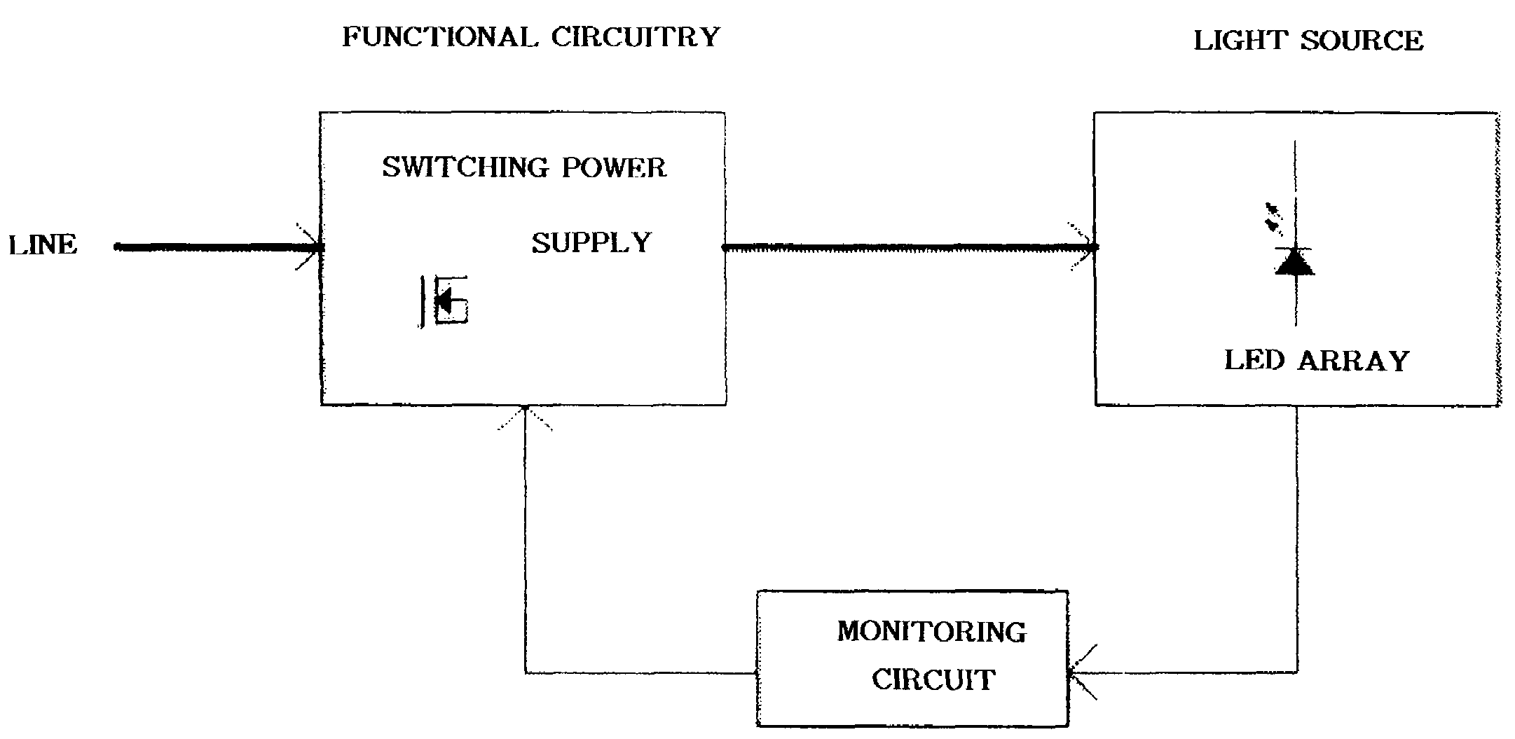
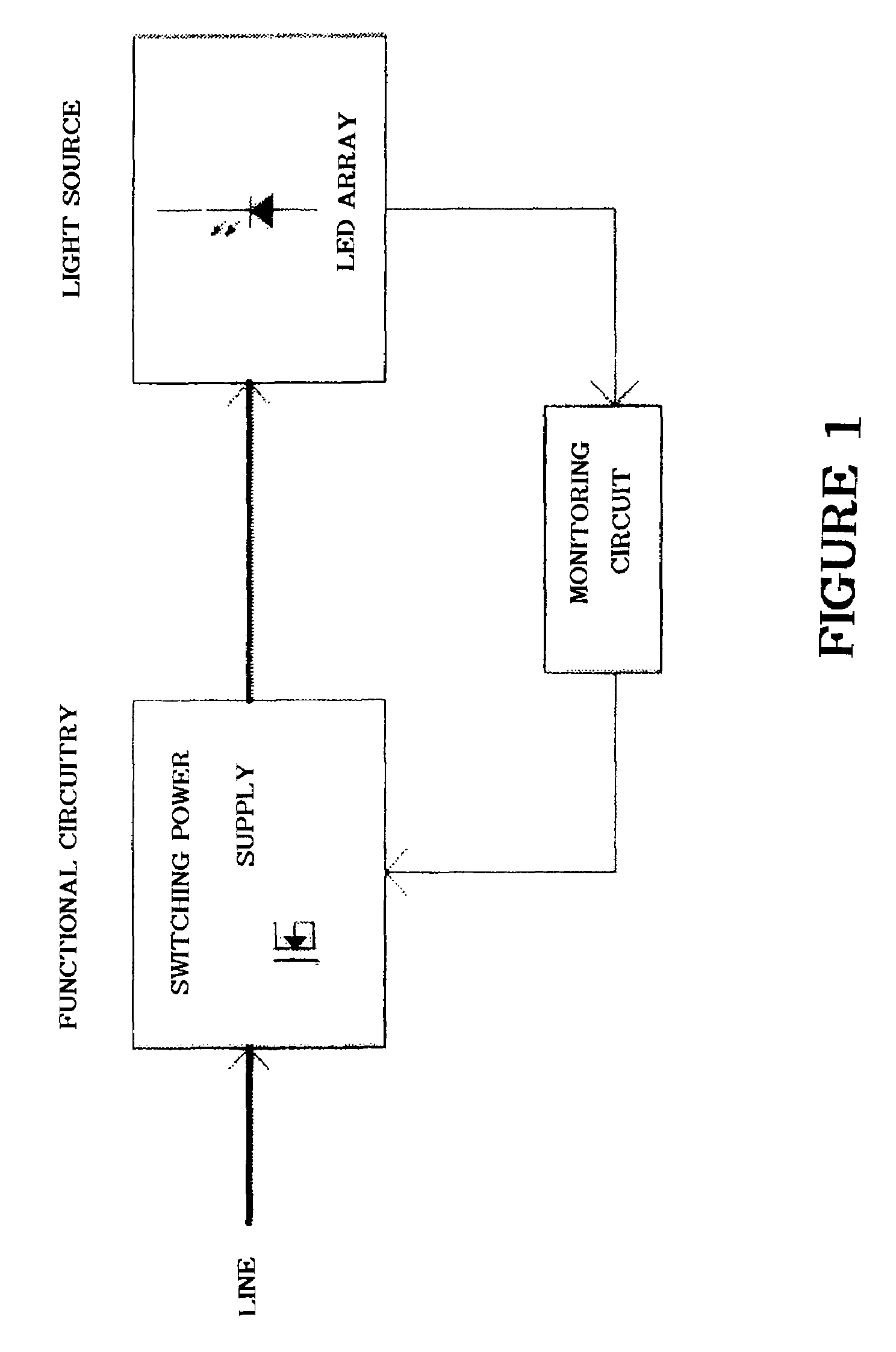
[0031]The inventive circuitry module includes functional circuitry, an LED light source array connected in series and parallel and configured for redundancy and a monitoring circuit. The functional circuitry preferably includes a switch mode power supply that converts 120 volts ac input voltage to an output constant current. For yellow LEDs, the output current is 900 mA. For red LEDs, the current output is 590 mA at 25° C. and 800 mA at 74° C. for green LEDs, the current output is 660 mA...


PUM


Abstract

A system is employed to provide a substantially constant intensity light source via functional circuitry, the functional circuitry comprises a switching power supply. At least one signal is part of a matrix of LEDs connected in series and parallel and configured for redundancy. A monitoring circuit comprises a current sense circuit, wherein the current sense circuit includes an amplifier and at least one resistor in series with the amplifier. The current sense circuit includes a power converter circuit that senses a current of a flyback diode, recovers a dc component of a waveform via a low pass filter, and provides feedback control of the at least one signal.

Description

BACKGROUND OF THE INVENTION[0001]1. Field of the Invention[0002]The present invention relates to a temperature dependent current sense circuit for a substantially constant intensity light source. Specifically, the present invention relates to a current sense circuit for a LED matrix for use in signal lights such as traffic lights.[0003]2. Description of the Prior Art[0004]The light-emitting diode (LED) produces light when a forward current flows thru its P-N junction. The intensity of the emitted light is directly proportional to the forward current, IF, and is maintained constant by regulating IF. Changing If according to the temperature profile of the LED performs thermal compensation of the light intensity.[0005]The light-emitting diode (LED) can be driven by a constant voltage, VF, to get the desired forward current, IF, or to regulate directly IF. The non-linear electrical characteristic of IF / VF has a logarithmic profile. Regulating IF by using the voltage driven method will r...

Claims


Application Information

Patent Timeline
Patent Type & Authority Patents(United States)
IPC IPC(8): G08G1/095G09F9/33G08B5/22H01L27/15H05B44/00
CPCH05B33/0815H05B33/0851H05B33/0884Y02B20/347H05B45/10Y02B20/30H05B45/3725H05B45/14
Inventor GELINAS, REYNAID
Owner GE LIGHTING SOLUTIONS LLC
Why Eureka
Try Eureka