[0011]It is a feature and
advantage of the present invention to provide a device and method of commutation control for an isolated
boost converter that minimizes energy that is wasted in a clamp circuit by creating a momentary
short circuit on the secondary winding of the
transformer, thereby improving efficiency and minimizing the size of the clamp circuit.
[0012]It is a further feature and
advantage of the present invention to provide a device and method of commutation control for an isolated boost converter that creates proper switching conditions to eliminate oscillation due to parasitic parameters by appropriate timing of the turn-on of secondary switches.
[0013]To achieve the stated and other features, advantages and objects, an embodiment of the present invention provides a
soft switching commutation control scheme for isolated boost
converters in which current in the leakage
inductance of the transformer is preset to significantly reduce the mismatch current with the inductor during commutation, thereby significantly reducing the
power rating for the
voltage clamp circuit for the
low voltage inverter. Thus, a simple passive clamp circuit becomes feasible. A unique
control logic implements a partial resonant and then freewheeling operation from the
high voltage side to achieve leakage current presetting. This control scheme makes use of parasitic parameters, such as transformer leakage
inductance and
transistor output junction capacitors, and the operation is insensitive to these parasitic parameters. Natural
soft switching is achieved for the transistors at the
high voltage side, which leads to lower switching loss and lower
electromagnetic interference (EMI).
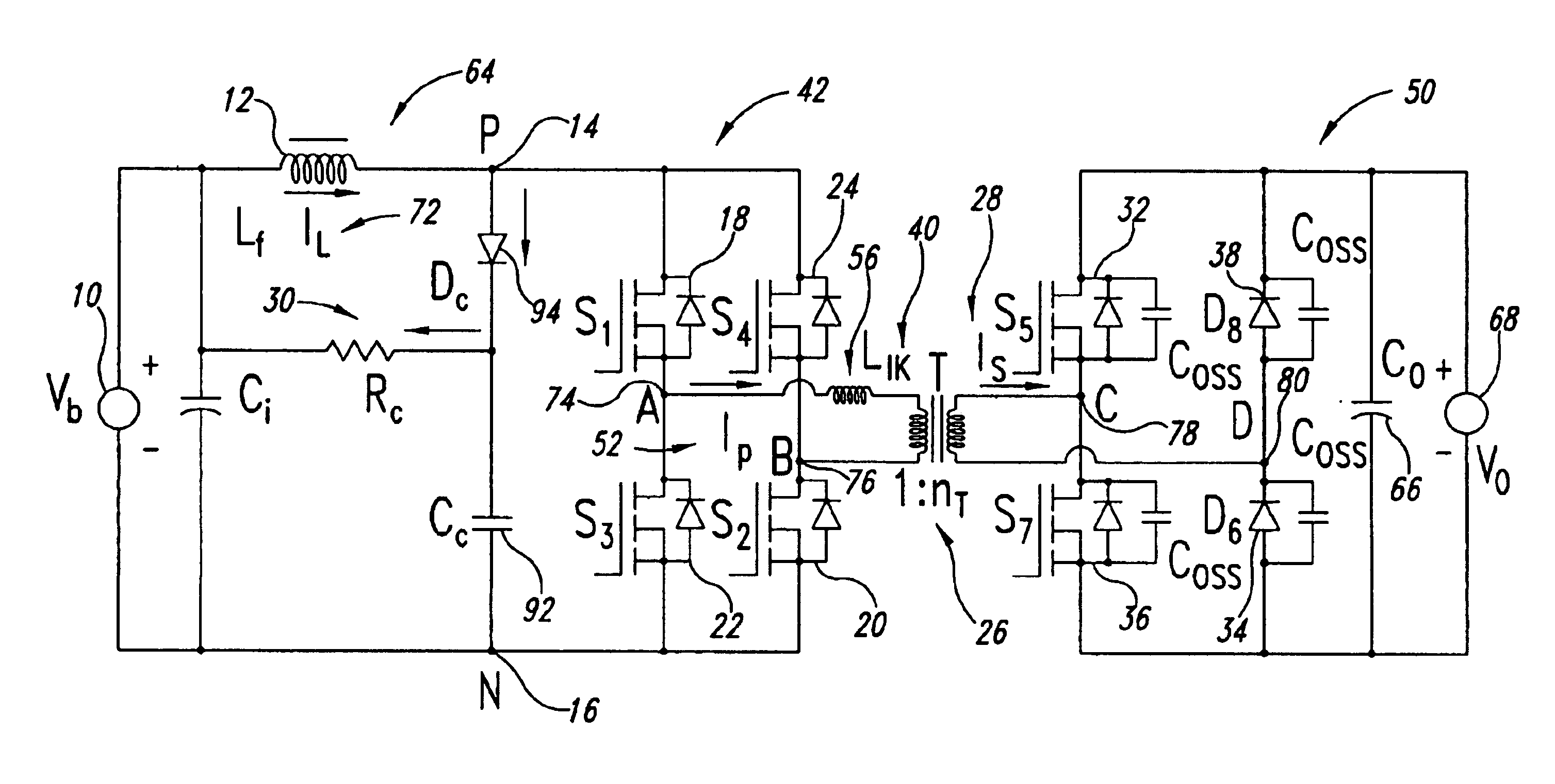
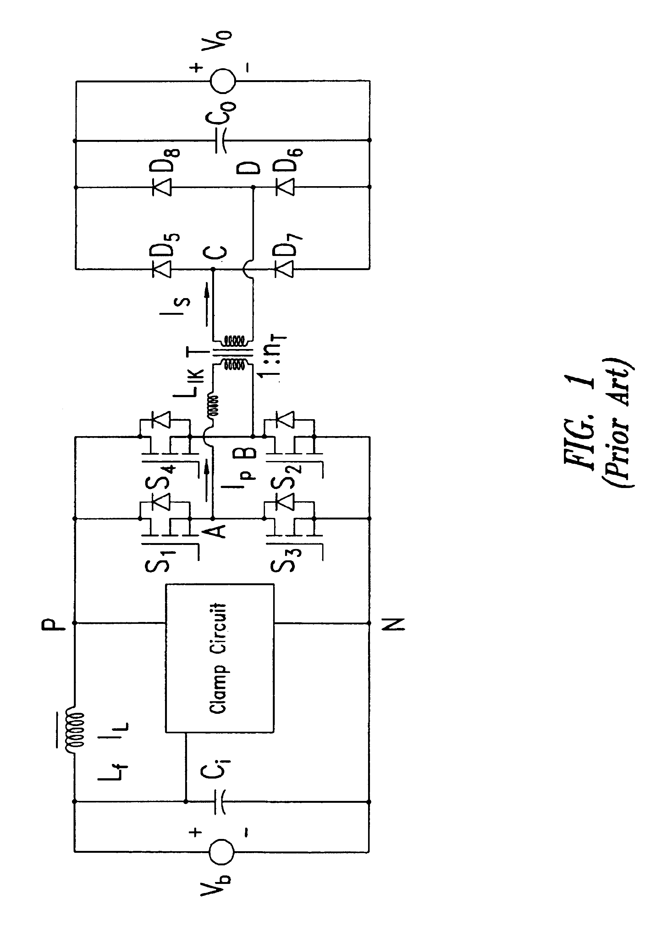
[0014]An embodiment of the present invention utilizes, for example, an inductor capable of storing energy from a direct current power source, such as a DC battery, an
inverter circuit coupled to the inductor capable of converting direct current to
alternating current, a transformer coupled to the
inverter and having a primary and a secondary and capable of stepping up
voltage of the
alternating current, and a
rectifier circuit coupled to the transformer that is capable of converting the stepped up
alternating current to direct current for delivery to a load. In addition, a programmable controller is pre-programmed with a commutation logic whereby, in a charging inductor switching mode of the inverter circuit that is timed to occur between alternating positive and negative current switching
modes of the inverter circuit, energy from the direct current power source is stored in the inductor, and the leakage
inductance current of the transformer is preset to a value close to the inductor current by short circuiting the transformer secondary during the charging inductor switching mode of the inverter circuit.
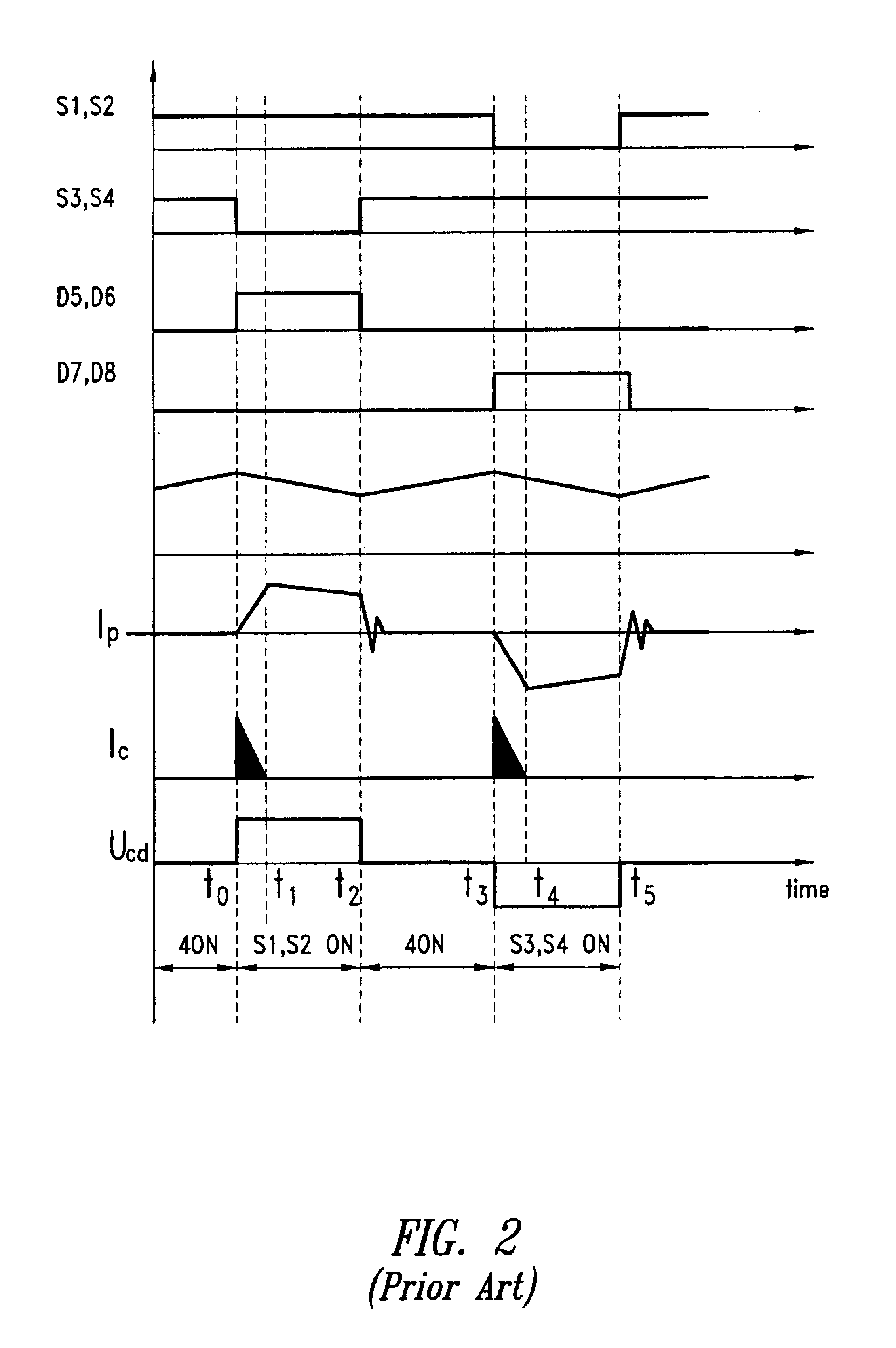
[0015]The inverter circuit includes, for example, first, second, third and fourth switches (S1, S2, S3, and S4), and the programmable controller is programmed with commutation logic whereby, in the charging inductor switching mode of the inverter circuit, the primary is short circuited with the first, second, third and fourth switches (S1, S2, S3, and S4) turned on. In the
positive current switching mode, the first and second switches (S1 and S2) are turned on and the third and fourth switches (S3 and S4) are turned off, energy is transferred from the inductor to the secondary,
arid current in the transformer is positive. In the negative current switching mode, the third and fourth switches (S3 and S4) are turned on and the first and second switches (S1 and S2) are turned off, energy is transferred from the inductor to the secondary, and current in the transformer is negative.
[0016]The
rectifier circuit includes, for example, fifth, sixth, seventh, and eighth switches (S5, D6, S7, and D8), and the programmable controller is also programmed with commutation logic whereby the leakage inductance current of the transformer is preset to the value close to the input inductor current and the commutation of the leakage inductance current is accelerated. This is achieved by turning on either the fifth or seventh switches (S5 and S7) to
short circuit the secondary during the charging inductor switching mode of the inverter circuit. The sixth and eighth switches (D6 and D8), for example, are diodes. D8 is automatically on when S5 is turned on, while D6 is automatically on when S7 is turned on. Either the fifth (S5 with D8 automatically on) or seventh switch (S7 with D6 automatically on) is turned on during the positive and negative current switching
modes to create a momentary
short circuit on the secondary of the transformer to preset the leakage inductance current in the transformer to a predetermined value that approaches a current value in the inductor.

