Leaky wave microstrip antenna with a prescribable pattern

a microstrip antenna and prescribable technology, applied in the direction of leaky waveguide antennas, antenna details, antennas, etc., can solve the problems of spurious radiation and ohmic loss of microstrip antenna arrays

Inactive Publication Date: 2005-01-04
ANRITSU CORP
View PDF4 Cites 31 Cited by
  • Summary
  • Abstract
  • Description
  • Claims
  • Application Information

AI Technical Summary

Benefits of technology

The present invention addresses the limitations and disadvantages of the prior art by introducing a leaky-wave microstrip antenna to which an aperture distribution may be prescribed. This distribution requires that the antenna possess a variable leakage-constant profile along its length, and is chosen so as to yield an H-plane power-gain pattern having low sidelobes (<<12 db below the main beam). The leakage-constant profile is achieved by choosing appropriately the width and length of the antenna's radiating cells, wh

Problems solved by technology

This is because microstrip antenna arrays suffer from spurious radiation and ohmic losses associated with their corporate feed.
This pattern exhibits s

Method used


Image

  • Leaky wave microstrip antenna with a prescribable pattern
  • Leaky wave microstrip antenna with a prescribable pattern
  • Leaky wave microstrip antenna with a prescribable pattern

Examples


Embodiment Construction

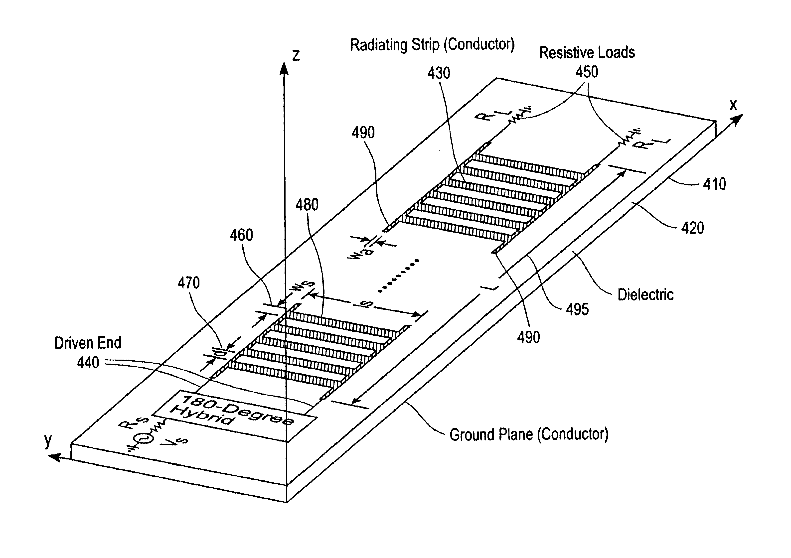
An amplitude distribution may be prescribed to a leaky-wave antenna having a periodical radiator cell structure. This distribution requires that the antenna possess a variable leakage-constant profile along its length, and is chosen so as to yield an H-plane power-gain pattern having low sidelobes. The leakage-constant profile is achieved by configuring the width and length of the antenna radiating cells while keeping the phase constant fixed. The length or loading of the radiating cells may also be manipulated to achieve the desired leakage constant profile. This results in the desired amplitude distribution along the antenna's aperture and yields a low-sidelobe power-gain pattern. The antenna is excited by two equal-amplitude and 180° out-of-phase signals. These signals are applied to the feed end of the microstrip at two feeding ports. The microstrip antenna length is chosen such that more than 97% of the input power is radiated by the traveling electromagnetic wave, while the re...


PUM


Abstract

A system and method for prescribing an amplitude distribution to a leaky-wave microstrip antenna having an array of radiating cells. The leaky-wave microstrip antenna includes a grounded element, a dielectric member coupled to the grounded element and a top conducting strip coupled to the dielectric member, the conducting strip including a first and second non-radiating conducting strip and a plurality of radiating cells. This distribution requires that the microstrip antenna possess a variable leakage-constant profile along its length, and is chosen so as to yield an H-plane power-gain pattern having low sidelobes. The leakage-constant profile is achieved by configuring the width and inter-cell spacing of the antenna radiating cells and keeping the phase constant fixed. The length or loading of the radiating cells may also be manipulated to achieve the desired leakage constant profile. This results in the desired distribution along the antenna's aperture and yields a power-gain pattern with low sidelobes. The antenna is excited by two equal-amplitude and 180° out-of-phase signals. These signals are applied to the feed end of the microstrip at two feeding ports. The microstrip antenna length is chosen such that more than 97% of the input power is radiated by the traveling electromagnetic, wave, while the remaining power is absorbed by the resistively terminated antenna end.

Description

FIELD OF THE INVENTIONThe current invention relates generally to leaky wave antennas, and more particularly to leaky-wave microstrip antennas having a prescribable power pattern.BACKGROUND OF THE INVENTIONLeaky wave antennas are electromagnetic traveling-wave radiators receiving a feed signal at one end and terminated in a resistive load at the other. The feeding end is used to launch a wave that travels along the antenna while leaking energy into free space. Power remaining in the traveling wave as it reaches the antenna end is absorbed by the resistive load. Using a single feed signal to excite a leaky-wave antenna results in higher radiation efficiency than in a microstrip antenna array. This is because microstrip antenna arrays suffer from spurious radiation and ohmic losses associated with their corporate feed. The aforementioned features of leaky-wave antennas make them well suited for operation at high frequencies.In 1979, Menzel introduced a traveling-wave microstrip antenna...

Claims


Application Information

Patent Timeline
IPC IPC(8): H01Q1/38H01Q13/00H01Q13/20
CPCH01Q13/206H01Q1/38
Inventor NOUJEIM, KARAM MICHAEL
Owner ANRITSU CORP
Why Eureka
Try Eureka