
Magnetic track following servo algorithm using signal quality

a servo algorithm and magnetic track technology, applied in the direction of track following on tapes, maintaining head carrier alignment, instruments, etc., can solve the problems affecting the accuracy of the signal, and the limiting factor of random lateral tape motion (“ltm”), so as to achieve the effect of reducing the bit error ra

Inactive Publication Date: 2005-01-04
QUANTUM CORP
View PDF11 Cites 36 Cited by
  • Summary
  • Abstract
  • Description
  • Claims
  • Application Information

AI Technical Summary

Benefits of technology

Particular implementations of the invention may provide one or more of the following advantages. The need for recorded servo information and / or servo heads for positioning read heads are eliminated. Also, because read data signal quality values (i.e., error signals) are a finer determiner of center of track than read data signal amplitude, bit error rates are reduced. In addition, the search for the lowest level of error (or noise) enables track following through shifts in track location in a manner that, unlike prior head positioning techniques, avoids placing a head at or near the edge of a data track where it can be knocked off of the track by even minor disturbances.

Problems solved by technology

In multi-track magnetic tape storage systems, random lateral tape motion (“LTM”) is a limiting factor in achieving higher track densities and higher user data capacity per tape.
Some may cause abrupt momentary jumps while others may cause a gradual shift over time.
During a read, LTM causes mis-registration of the read head over the track being read.
Such mis-registration results in read data error.

Method used


Image

  • Magnetic track following servo algorithm using signal quality
  • Magnetic track following servo algorithm using signal quality
  • Magnetic track following servo algorithm using signal quality

Examples


Embodiment Construction

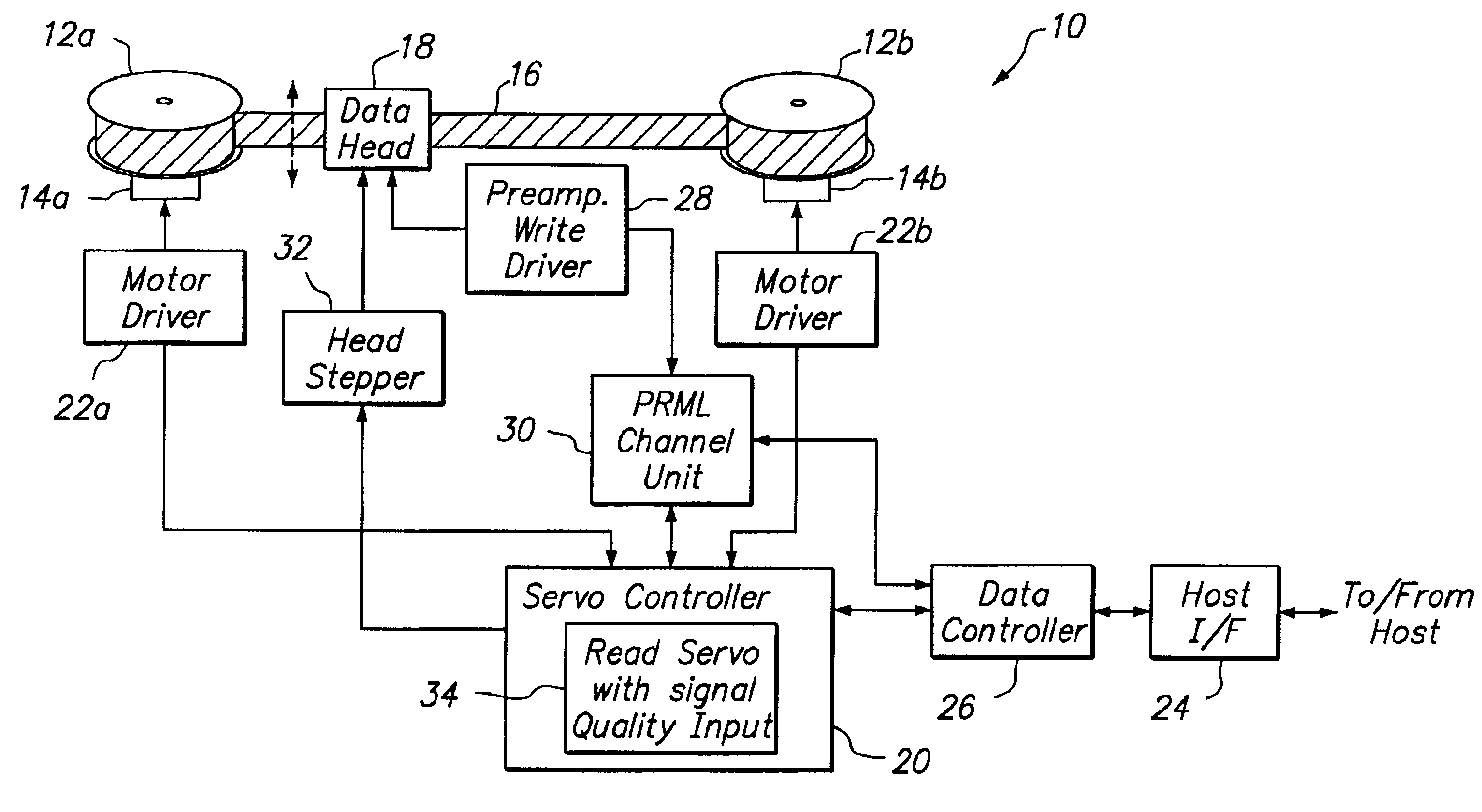
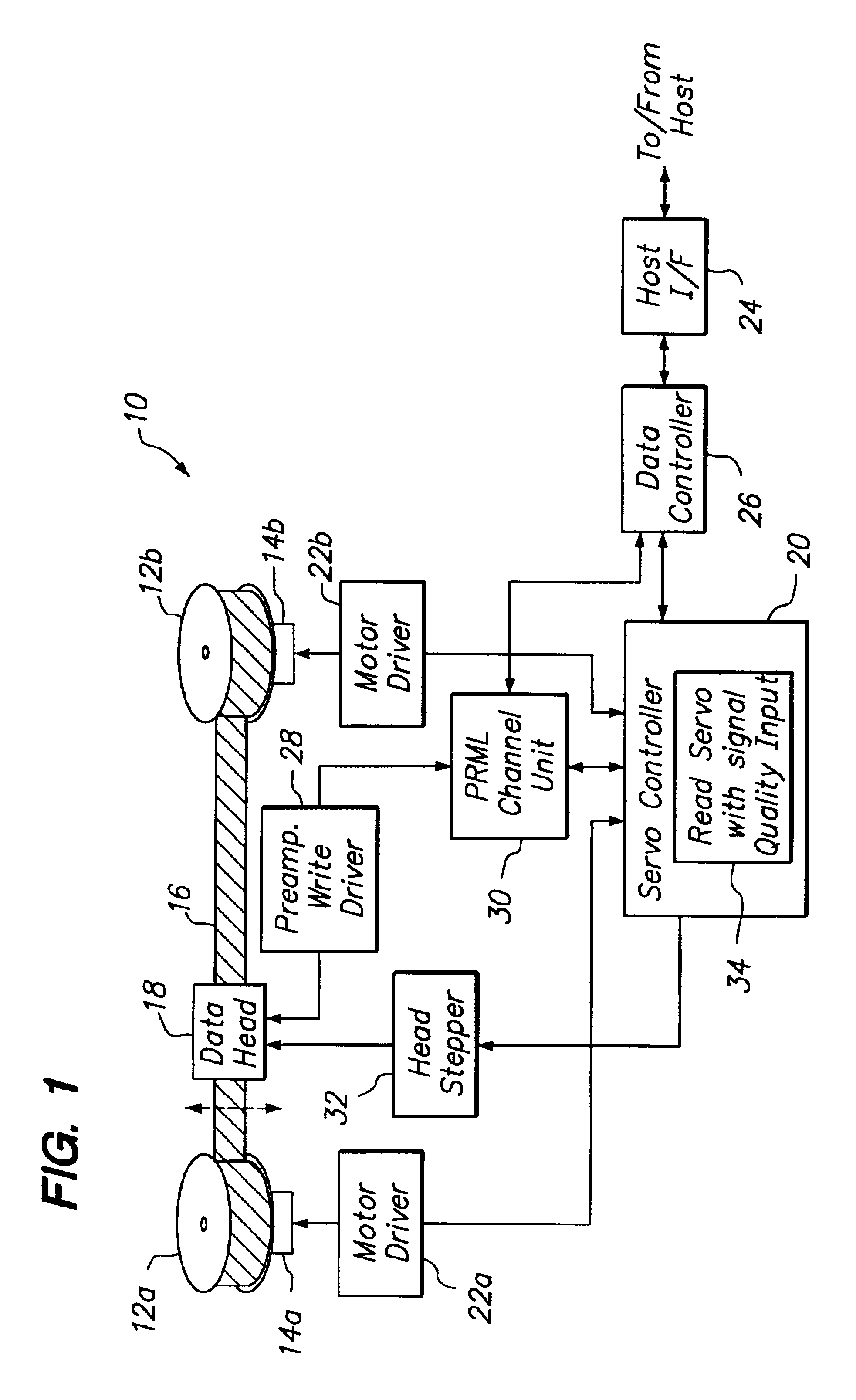
Referring to FIG. 1, an exemplary magnetic tape drive system 10 is shown. The tape drive system 10 includes a tape transport system schematically represented by two reels 12, a supply reel 12a and a take-up reel 12b, mounted on rotatably driven tape transport motors 14a, 14b, respectively. The tape transport motors 14 rotate the reels 12 to transport a tape 16 from one reel to the other. The tape 16 has one or more longitudinal tracks of data recorded thereon. As the tape advances, it moves past a data head structure 18, which simultaneously reads from one of the data tracks on the tape 16. The data head structure 18 includes at least one read head. It can also include additional data heads for reading and / or writing data, and the other data heads may access data in the same format or in a different format. Typically, although not shown, the tape transport system 10 also includes a tachometer for sensing the tape speed and a sensor for detecting the beginning and end of tape.

As used...


PUM


Abstract

A read servo mechanism that uses levels of read data signal quality to maintain track centerline is presented. In a seek operation mode, a baseline signal quality value is sampled at a current tracking position and, once the baseline signal quality value is established, the head is stepped to change its position and the signal quality value sampled after each position change to determine change in signal quality until the change in signal quality is found to be insignificant. After a predetermined interval, the signal quality value is again sampled. If the signal quality value has changed significantly or the time that has expired since the seek operation mode ended is greater than some larger interval, the seek operation is repeated in an effort to search for a new baseline level of signal quality (and, therefore, the new track center).

Description

BACKGROUND OF THE INVENTIONThe invention relates generally to head positioning servo systems for reducing misalignment between heads and data tracks in data storage systems.In multi-track magnetic tape storage systems, random lateral tape motion (“LTM”) is a limiting factor in achieving higher track densities and higher user data capacity per tape. LTM is the random motion of a tape in a direction lateral to the direction of tape transport. LTM is impacted by variations in tension, number of tape guides used, as well as other factors. These factors affect LTM in various ways. Some may cause abrupt momentary jumps while others may cause a gradual shift over time. During a read, LTM causes mis-registration of the read head over the track being read. Such mis-registration results in read data error.Various servo techniques or approaches have been developed to reduce the effects of tracking error caused by LTM and thus improve track density. Although known servo techniques vary somewhat...

Claims


Application Information

Patent Timeline
IPC IPC(8): G11B5/584
CPCG11B5/584
Inventor TRIVEDI, HITESH
Owner QUANTUM CORP
Learn More