Protection system for protecting a poly-phase distribution transformer insulated in a liquid dielectric, the system including at least one phase disconnector switch

a protection system and poly-phase technology, applied in emergency protective devices, emergency protective circuit arrangements, transformer/inductance details, etc., can solve problems such as dielectric spraying around, transformer explosion, and excessive internal pressure, and achieve the effect of avoiding excessive internal pressur

Inactive Publication Date: 2005-01-04
AREVA T&D
View PDF6 Cites 42 Cited by
  • Summary
  • Abstract
  • Description
  • Claims
  • Application Information

AI Technical Summary

Benefits of technology

In yet another particular embodiment of the protection system of the invention, the rod is disposed inside a housing provided with vents. The housing is normally filled with the dielectric, and the vents make it possible to avoid excessive internal pressure when the dielectric expands in the normal operating stages of the transformer. In addition, the vents makes it possible to remove gases that can form when the rod slides, and also to fill the housing under a vacuum with the dielectric contained inside the tank.

Problems solved by technology

In a distribution transformer having liquid dielectric, in the event of a fault there is a risk of the dielectric overheating, thereby giving rise to excessive pressure that can reach a value so high that the transformer explodes.
There is then a risk that the dielectric might be sprayed around, with serious consequences on the environment.

Method used


Image

  • Protection system for protecting a poly-phase distribution transformer insulated in a liquid dielectric, the system including at least one phase disconnector switch
  • Protection system for protecting a poly-phase distribution transformer insulated in a liquid dielectric, the system including at least one phase disconnector switch
  • Protection system for protecting a poly-phase distribution transformer insulated in a liquid dielectric, the system including at least one phase disconnector switch

Examples


Embodiment Construction

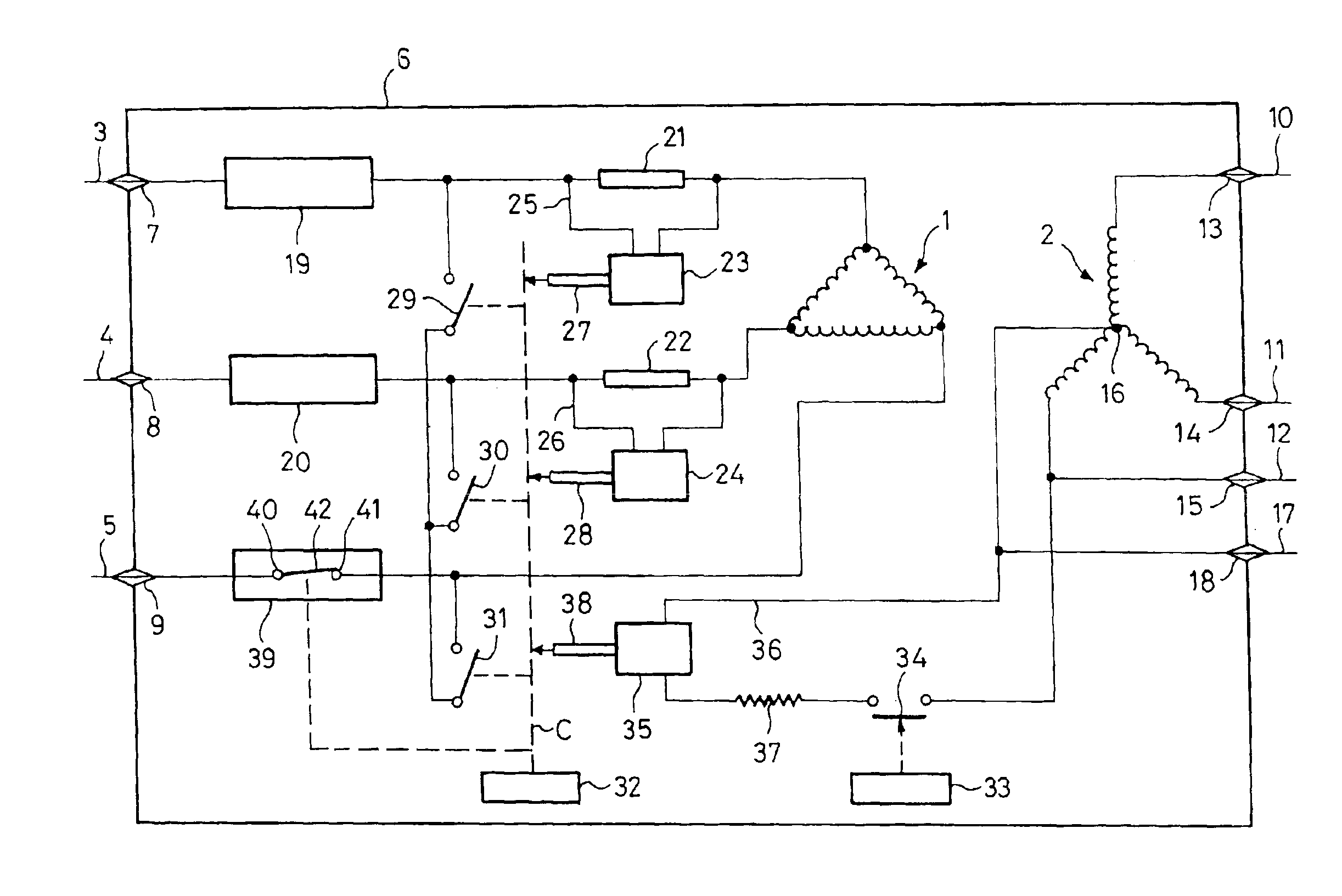
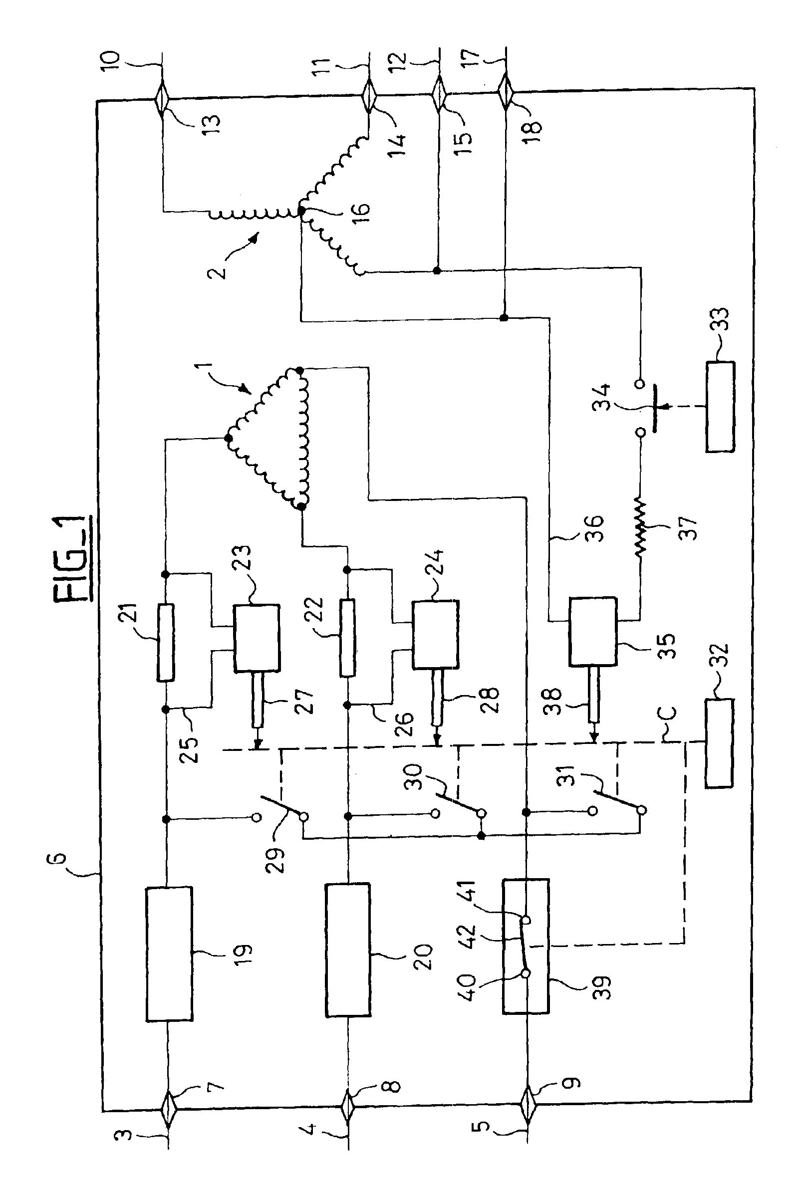
The transformer shown in FIG. 1 may, for example, be a 20 / 0.410 kilovolt (kv) transformer. Reference 1 designates the delta high-voltage winding and reference 2 designates the star low-voltage winding. The high-voltage winding 1 is powered via the three phases 3, 4, and 5 which penetrate in leaktight manner via insulating feedthroughs 7, 8, and 9 into the tank of the transformer, which is diagrammatically represented by a rectangle 6.

The low-voltage winding 2 feeds the phase lines 10, 11 and 12 by passing through the tank 6 in leak-tight manner via insulating feedthroughs 13, 14, and 15, and similarly, the neutral point 16 is connected to a neutral conductor 17 passing through the tank in leaktight manner via an insulating feedthrough 18.

On the high-voltage side, two of the three phases (the phases referenced 3 and 4 in this example) are connected to the high-voltage winding 1 via respective current-limiting fuses 19 and 20.

These fuses function normally above a current referred to a...


PUM


Abstract

The distribution transformer is installed in a station having N phases, at least N-1 phases being equipped on the high-voltage side of the transformer with respective current-limiting fuses capable of blowing in the event of a dead short circuit between the phases. The protection system includes: at least one fault detector for detecting faults on the basis of at least one of the following indicators: pressure in the tank, level of the dielectric, or temperature of the transformer; a short-circuiter acting on all the phases situated upstream from the high-voltage windings, said short-circuiter being capable of being triggered by said fault detector to establish a dead short circuit between the phases; and on at least N-1 phases, a detector for detecting an abnormal current upstream from the transformer, said detector being associated with a controller for controlling said short-circuiter. In the system, at least the phase that is not equipped with a limiting fuse is equipped with a disconnector switch which is normally closed in the absence of any fault, said disconnector switch being disposed on the high-voltage side of the transformer upstream from the short-circuiter, and opening thereof being triggered by the short-circuiter in the event of a fault, but with a certain delay.

Description

The invention relates to a protection system for protecting a distribution transformer insulated in a liquid dielectric.BACKGROUND OF THE INVENTIONIn a distribution transformer having liquid dielectric, in the event of a fault there is a risk of the dielectric overheating, thereby giving rise to excessive pressure that can reach a value so high that the transformer explodes. There is then a risk that the dielectric might be sprayed around, with serious consequences on the environment.French Patent Application FR2801141 describes a protection system making it possible to prevent the transformer from exploding. In that protection system for protecting a three-phase distribution transformer immersed in a liquid dielectric contained in a tank, two of the three phases are equipped on the high-voltage side of the transformer with respective current-limiting fuses, and with respective protection micro-fuses disposed in series with the corresponding current-limiting fuse, each of said micro...

Claims


Application Information

Patent Timeline
Patent Type & Authority Patents(United States)
IPC IPC(8): H01H79/00H02H7/04H01H9/10H01H9/00
CPCH02H7/04H01H79/00H01F27/402H01H9/104
Inventor FOLLIOT, PHILIPPEMELQUIOND, STEPHANEHEBERT, FRAN.CEDILLA.OISGRAVE, PATRICE
Owner AREVA T&D
Why Eureka
Try Eureka