Module for measuring purposes

a module and measuring technology, applied in the direction of electrical apparatus construction details, coupling device connections, support structure mounting, etc., can solve the problems of limited system usefulness, system is not freely scalable, and the rack can only hold a limited number of slide-in cards

Inactive Publication Date: 2005-01-04
TESTO AG
View PDF34 Cites 45 Cited by
  • Summary
  • Abstract
  • Description
  • Claims
  • Application Information

AI Technical Summary

Benefits of technology

Thus, the task of the invention is to provide a system which no longer has the disadvantages mentioned above. Especially, a system should be provided which is freely scalable in any arbitrary manner and is not limited by the size of the rack. In addition, use at almost any arbitrary location should be possible. Finally, it should be useable both for very simple as well as complicated measuring purposes.

Problems solved by technology

Although such systems were found to be useful, an inherent disadvantage is that the rack can hold only a limited number of slide-in cards.
Therefore, such a system is not freely scalable, but is always limited by the size of the corresponding rack.
In addition, because of this predetermined constructional size, such a system has limited usefulness for the so-called portable measuring technique.

Method used


Image

  • Module for measuring purposes
  • Module for measuring purposes
  • Module for measuring purposes

Examples


Embodiment Construction

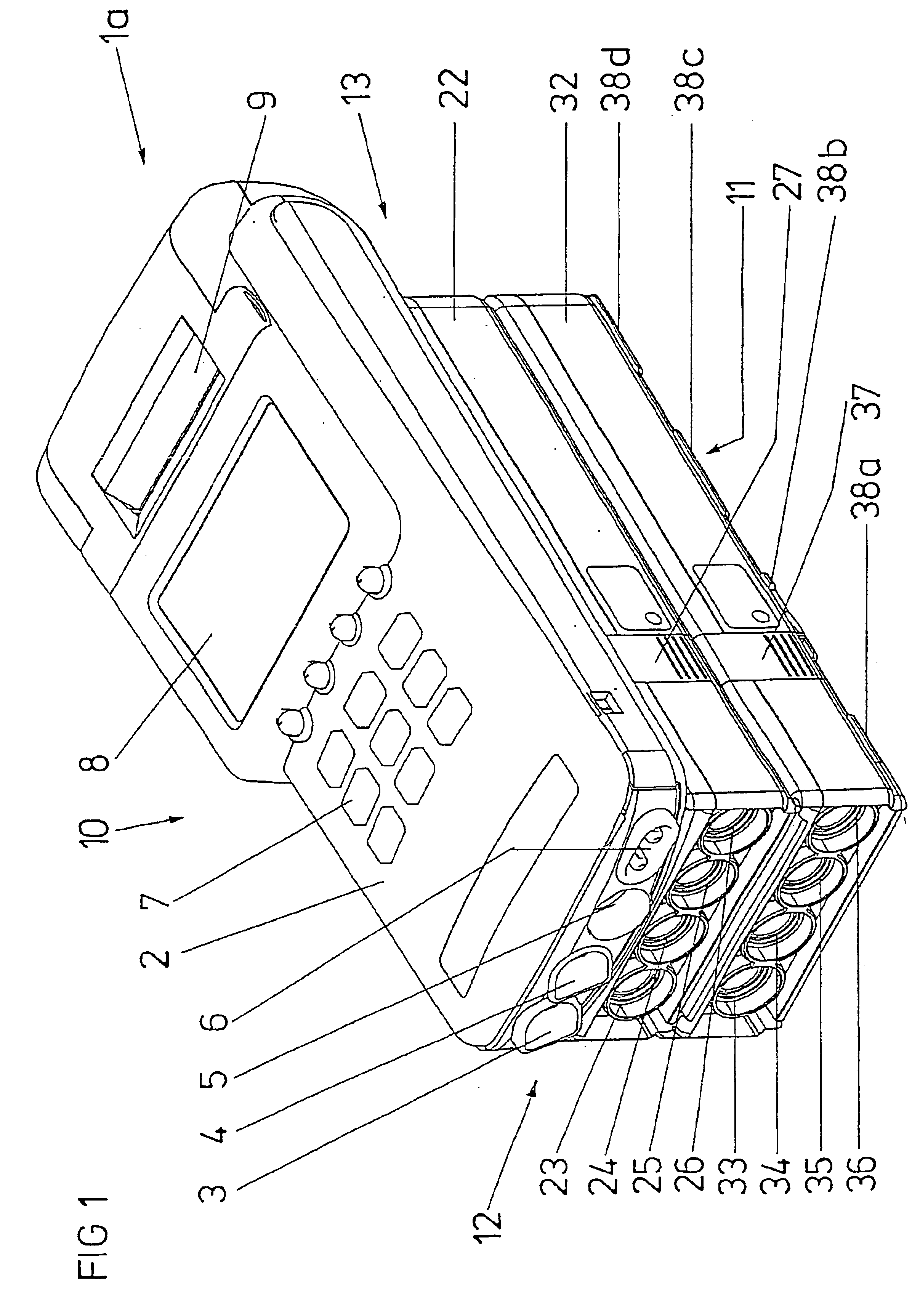
FIG. 1 shows a measuring unit 1 a consisting of several individual modules 2, 22, 32 according to the invention. Specifically, the measuring unit 1a, shown in FIG. 1, has a combined operating, measuring, display and printing module 2, a measuring module 22 connected with this and another measuring module 32 connecting to the latter.

The operating, measuring, display and printing module 2, as it is obvious from the name, has a keyboard 7 for data input and thus for operation of module 2, a measuring channel connection 5 to connect it with a measuring cell, a measured value recorder, a sensor or similar. Furthermore, a display 8 is provided in order to display the measured value introduced to measurement channel connection 5 and as well as a small printer 9, for example, to produce a measuring or data protocol. Furthermore, the operating, measuring, display and printing module 2 has a sending element 3 and a receiving element 4, through which data communication, for example, via radio,...


PUM

PropertyMeasurementUnit
tip radiusaaaaaaaaaa
forceaaaaaaaaaa
contact surfacesaaaaaaaaaa

Abstract

The invention relates to a module for measuring purposes comprising an electrical or electronic circuit, which has at least one power supply connection and at least one data line connection for connecting, in the manner of a bus, to at least one other module of the same type that is also used for measuring purposes. According to the invention, the electronic circuit (80) is arranged inside a housing, the housing has a first contact surface (90) and a second contact surface (91), and the first contact surface (90) is joined to the second contact surface (91) of the other module (22, 32, 42) in a manner that permits it to be mechanically detached. The at least one power supply connection has a power supply contact (84a, 85a) in the first contact surface (90) and has a corresponding power supply contact (84b, 85b) in the second contact surface (91). The at least one data line connection has a data line contact (86a, 87a) in the first contact surface (90) and has a corresponding data line contact (86b, 87b) in the second contact surface (91). When the first contact surface (90) is joined to the second contact surface (91) of the other module (22, 32, 42), the power supply contact (84a, 85a) in the first contact surface (90) is connected in an electrically conductive manner to the corresponding power supply contact (84b, 85b) in the second contact surface (91) of the other module (22, 32, 42), and the data line contact (86a, 87a) in the first contact surface (90) is connected in an electrically conductive manner to the corresponding data line contact (86b, 87b) in the second contact surface (91) of the other module (22, 32, 42).

Description

BACKGROUND OF THE INVENTION1. Field of the InventionThe invention concerns a module for measuring purposes according to the main clause of claim 1.2. Description of the Related ArtHousings or racks are known from the state of the art into which a limited number of so-called slide-in cards can be inserted. Among those working in this field, these are known by the name 19″-rack or the like.Such modularly built slide-in cards, preferably boards carrying an electrical or electronic circuit, usually have one or more power supply connections and one or more data line connections, which are inserted into the plug arrangements located at the back of the corresponding rack, by inserting the slide-in cards into one of the racks described above.As a rule, all the plug arrangements provided on the back side of a rack are of similar design and the corresponding contacts of the individual slots are connected together via an electrical connection. In this way, it is achieved that the slide-in card...

Claims


Application Information

Patent Timeline
Patent Type & Authority Patents(United States)
IPC IPC(8): H05K7/14H05K5/02G01N33/00
CPCH05K5/0021H05K7/1435Y10S439/928
Inventor DERR, ANDREASSTREICHER, MANFREDSCHULZ, PETER
Owner TESTO AG
Why Eureka
Try Eureka