
Adaptive DS-CDMA multi-user receiver with diversity combining for interference cancellation

a multi-user receiver and diversity technology, applied in diversity/multi-antenna systems, multiple modulation transmitter/receiver arrangements, baseband system details, etc., can solve the problems of limiting the performance of the network, prior art digital receivers are generally characterized by a fairly high computational complexity, and the computational complexity lies on the block-based processing of the receiver

Inactive Publication Date: 2005-01-04
MITSUBISHI ELECTRIC RES LAB INC
View PDF7 Cites 23 Cited by
  • Summary
  • Abstract
  • Description
  • Claims
  • Application Information

AI Technical Summary

Benefits of technology

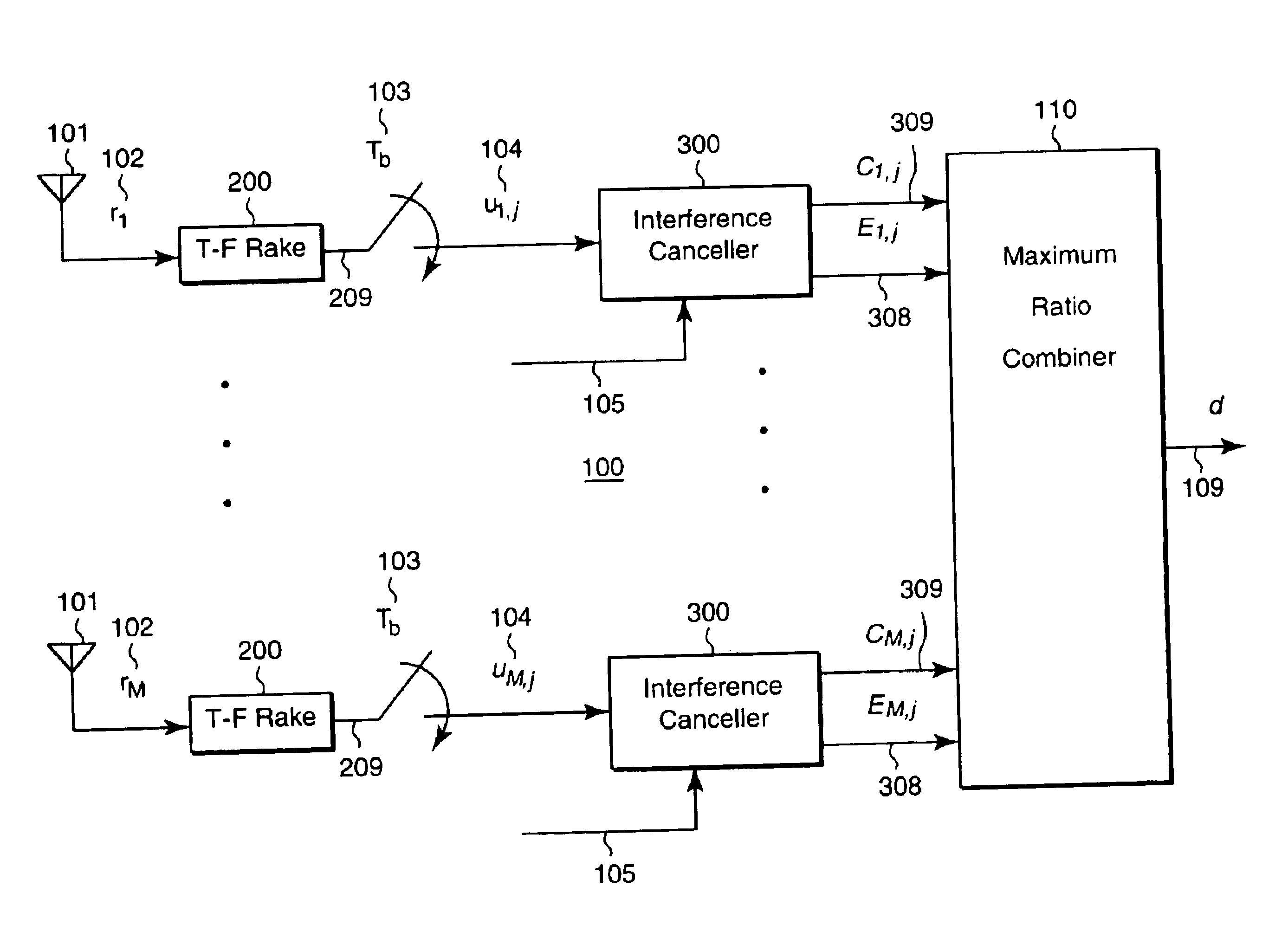
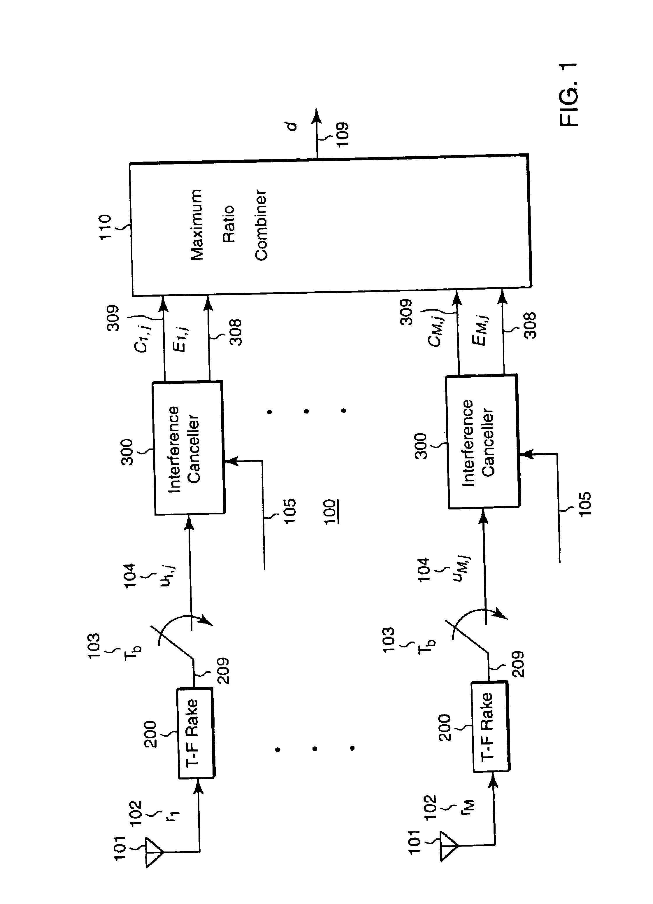
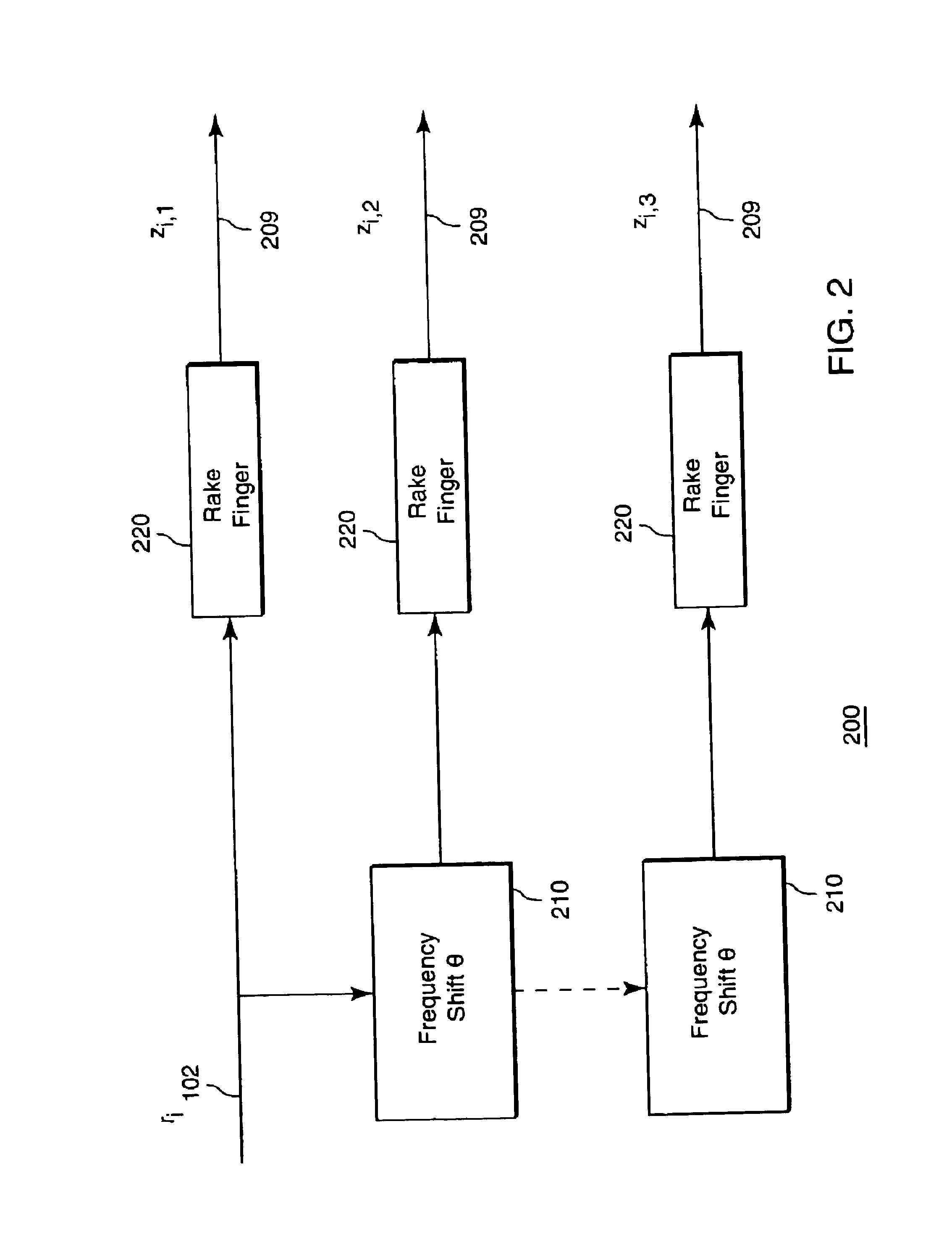
The present invention is an adaptive receiver that can detect multiple signals in a DS-CDMA network. It uses multiple antennas and a time-frequency rake receiver connected to each antenna. An interference canceller is connected to the output of each rake receiver, and a diversity combiner is connected to the output of each interference canceller. The diversity combiner determines decision symbols based on the input signals received at the antennas. The antennas are spaced about three to five times the wavelength of the baseband signals. The technical effect of this invention is to improve the detection of multiple signals in a DS-CDMA network.

Problems solved by technology

In a wireless CDMA communication network, multiple access interference (MAI) is one of the major factors that limits the performance of the network.
However, prior art digital receivers are generally characterized by a fairly high computational complexity.
The major cause of the computational complexity lies on the block-based processing in the receivers, i.e., the receivers detect the signal based on a block of received samples.
Channel fading is another cause of performance degradation in wireless communication networks.
The increased mobility of receivers in wireless communication networks often results in fast fading and the resulting Doppler spread substantially degrades the receiver performance.
However, in the case of a fast fading channel, little performance improvement can be achieved, even if the diversity dimension is increased.
However, that receiver can only detect a single user.

Method used


Image

  • Adaptive DS-CDMA multi-user receiver with diversity combining for interference cancellation
  • Adaptive DS-CDMA multi-user receiver with diversity combining for interference cancellation
  • Adaptive DS-CDMA multi-user receiver with diversity combining for interference cancellation

Examples


case 1

le transceiver (cell phone) does not have the T-F rake receiver. In this case, the compensation is done during the downlink transmission from the base station, because the mobile transceiver cannot estimate the frequency offset using Eq.(4).

As shown in FIG. 4, a compensator 500 determines the frequency offset Δfi and makes transmission carrier frequency adjustment by the offset Δfi. These adjusted carriers are used at each transmitter antenna 401 to modulate the transmitted data 501. A weight ωi 402, for i=1, 2, . . . , M, at each antenna 401 is used to produce antenna beamforming for the purpose of transmit diversity to improve system performance.

FIG. 5 shows the compensator 500 in greater detail. The frequency offset at ith antenna, Δfi, is first determined based on Eq.(4) and the carrier frequency fci is then adjusted by Δfi.

case 2

le transceiver has the T-F Rake receiver. In this case, the compensation is done at the mobile user side because the mobile receiver has the capability to estimate the frequency offset, and access to the network by the mobile receivers is random. Using a circuit similar to the one shown in FIG. 4, the mobile transmitter can make compensation in the uplink transmission.


PUM


Abstract

A digital receiver detects symbols in a baseband signal in a DS-CDMA network. The receiver includes multiple spaced apart antennas. A time-frequency rake receiver is connected to each of the antennas. An interference canceller is connected to each output of each of the rake receiver. Each interference canceller produces a contributing symbol in parallel. A diversity combiner determines a decision symbol corresponding to the baseband signal from the contributing symbols.

Description

FIELD OF THE INVENTIONThe present invention relates generally to wireless digital receivers, and more particularly to a wireless DS-CDMA communication network having multiple concurrent transmitters.BACKGROUND OF THE INVENTIONThe explosive growth of mobile telecommunication networks demands flexible, efficient, high performance receivers, for example, base stations in cellular networks. In a wireless CDMA communication network, multiple access interference (MAI) is one of the major factors that limits the performance of the network. To combat the effect of MAI, many digital receivers have been proposed. However, prior art digital receivers are generally characterized by a fairly high computational complexity.The major cause of the computational complexity lies on the block-based processing in the receivers, i.e., the receivers detect the signal based on a block of received samples. Multi-user receivers also require a great deal of additional information which typically includes a co...

Claims


Application Information

Patent Timeline
Patent Type & Authority Patents(United States)
IPC IPC(8): H04B1/40H04B7/26H04L25/02H04L27/00H04B1/707H04B7/08
CPCH04B1/0003H04B1/406H04L27/0008H04B7/2612H04L25/0228H04B1/707H04B7/0845
Inventor HORNG, JYHCHAUBAO, JAY
Owner MITSUBISHI ELECTRIC RES LAB INC
Learn More