RF signal repeater in mobile communications systems

a mobile communication system and signal repeater technology, applied in the field of rf signal repeaters, can solve the problems of increasing the bit error rate at the receiver, unstable feedback problem, and substantial feedback

Inactive Publication Date: 2005-01-04
APPLE INC
View PDF8 Cites 140 Cited by
  • Summary
  • Abstract
  • Description
  • Claims
  • Application Information

AI Technical Summary

Problems solved by technology

For both GPRS and EDGE receivers, as the SNR drops, the bit error rate at the receiver will increase.
An inherent problem of repeating a signal transmission with little or no frequency translation is that the retransmitted signal may feedback into an RF repeater's receiving antenna.
This unstable feedback problem is analogous to the familiar “howl” heard at public events when a speaker's microphone is too close to the loudspeakers.
Ordinarily, however, the RF repeater would not know the position of the mobile unit and would thus use an omni-directional antenna to communicate with the mobile unit.
Moreover, even with the use of directional antennas, near field effects are very unpredictable and could cause substantial feedback.
Such an arrangement of frequency translating repeat

Method used


Image

  • RF signal repeater in mobile communications systems
  • RF signal repeater in mobile communications systems
  • RF signal repeater in mobile communications systems

Examples


Embodiment Construction

g to one embodiment of the invention.

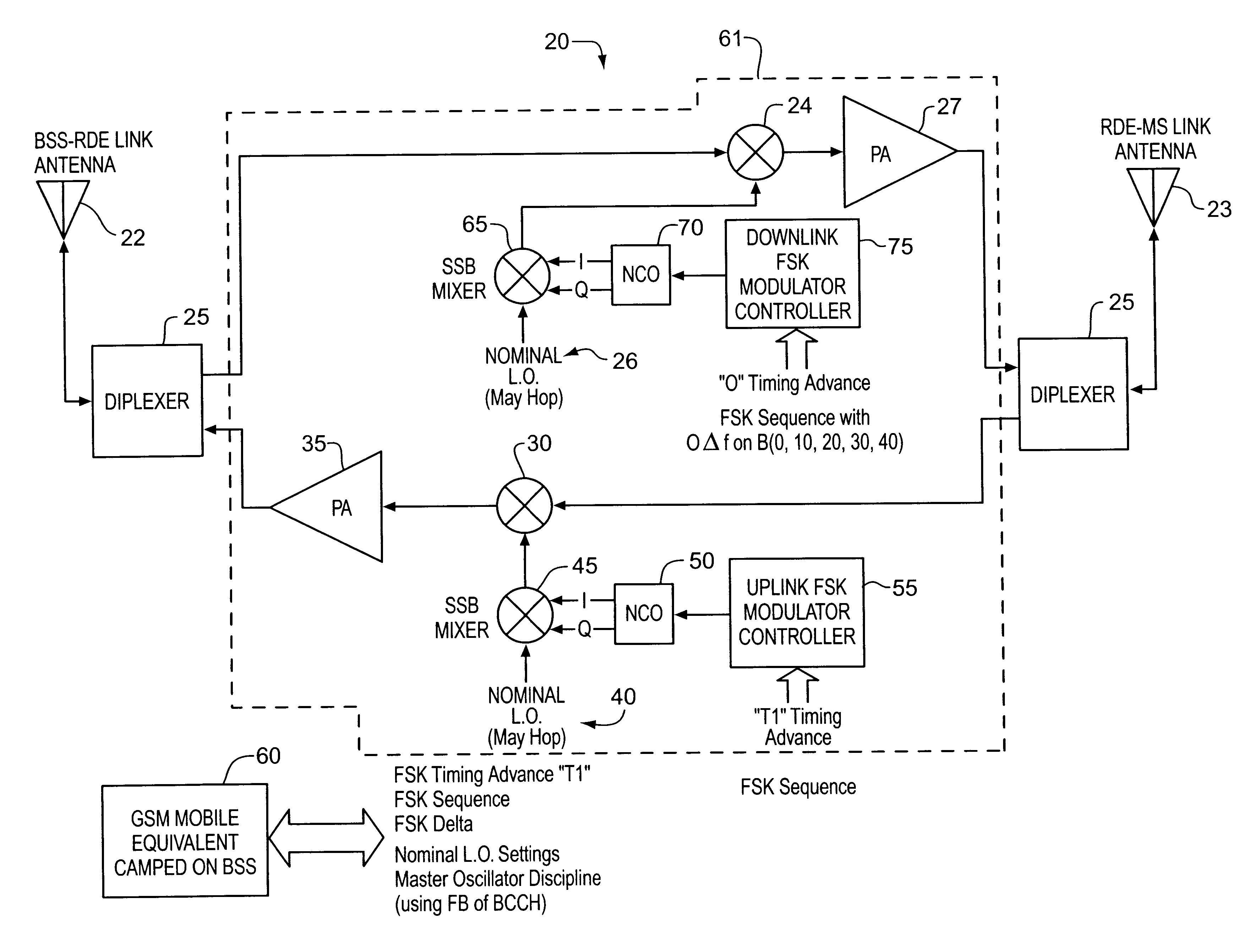
[0019]FIG. 3 shows a conceptual block diagram of an RF repeater with uplink and downlink signal tagging according to one embodiment of the invention.

[0020]FIG. 4 shows a conceptual block diagram of a location measurement unit with circuitry to detect tagged signals according to the present invention.

[0021]FIG. 5 shows the interaction between the location measurement unit and the mobile location center according to the present invention.

[0022]FIG. 6 illustrates the operation of an arctangent frequency discriminator.

DETAILED DESCRIPTION

[0023]Reference will now be made in detail to the present preferred embodiments of the invention, examples of which are illustrated in the accompanying drawings, wherein like reference numerals indicate like elements throughout the several views.

[0024]The invention provides RF repeaters with the ability to enhance signal to noise and interference ratios over selected areas within a given cell, in particular to enable...


PUM


Abstract

A RF signal repeater system is added to a wireless communications network which increases user data rates at the periphery of the cellular coverage area by boosting the downlink (base station to mobile user) signal and uplink (mobile user to base station) signal. The RF signal repeater system includes a signal tagging means that adds a unique electronic signature to the repeated signal such that position determination errors due to a non-line of sight propagation path can be corrected. The repeated signal is received and processed with a location measurement unit to determine the time of arrival and to extract the signal tag of the repeated signal. The time of arrival measurement and recovered signal tag are then processed at a mobile location center to determine the true position of the transmitter.

Description

CLAIM OF PRIORITY[0002]This is a continuation of application Ser. No. 09 / 596,653, filed on Jun. 19, 2000, now U.S. Pat. No. 6,501,955 B1.FIELD[0003]Embodiments of the invention relate to RF signal repeaters and more particularly, to the use of an RF signal repeater having an electronic signature imposed upon the repeated signal to allow identification of the signal repeater.BACKGROUND[0004]Wireless data services are used for remote access of e-mail, mobile Internet browsing, company information and others. To attract new and existing subscribers to data services, the operator need to support perceived data rates of 64 kbps or greater. Within GSM networks, two such services are General Packet Radio Service (GPRS) and Enhanced Data for GSM Evolution (EDGE). Both bring packet data connectivity to the GSM market at a variety of data rates. To support the high data rates in either service, however, requires increasing the signal-to-noise ratio (SNR) at the receiving handset. As a handset...

Claims


Application Information

Patent Timeline
IPC IPC(8): G01S11/00G01S11/02G01S5/14H04B7/26G01S19/25G01S19/48
CPCG01S5/14G01S11/02G01S5/0273H04B7/2606H04B7/155H04W16/26
Inventor DURRANT, RANDOLPH L.SCOTT, LOGANREECE, JOHN K.
Owner APPLE INC
Why Eureka
Try Eureka