
System for rapid manufacturing of replacement aerospace parts

a technology for aerospace parts and manufacturing methods, applied in the direction of total factory control, programme control, electric programme control, etc., can solve the problems of high cost, parts “as designed” may not in fact interface correctly into the existing system, and achieve the effect of rapid manufacturing and rapid manufacturing of aerospace replacement parts

Inactive Publication Date: 2005-01-04
THE BOEING CO
View PDF14 Cites 39 Cited by
  • Summary
  • Abstract
  • Description
  • Claims
  • Application Information

AI Technical Summary

Benefits of technology

It is therefore an object to the present invention to provide an apparatus and method for the rapid manufacturing of aerospace replacement parts that provides relief from the costs and long lead-time associated with the development and fabrication of tooling. It is further object to the present invention to provide an apparatus and method for the rapid manufacturing of aerospace replacement parts that would address small lot productions and components that no longer match original design configurations.
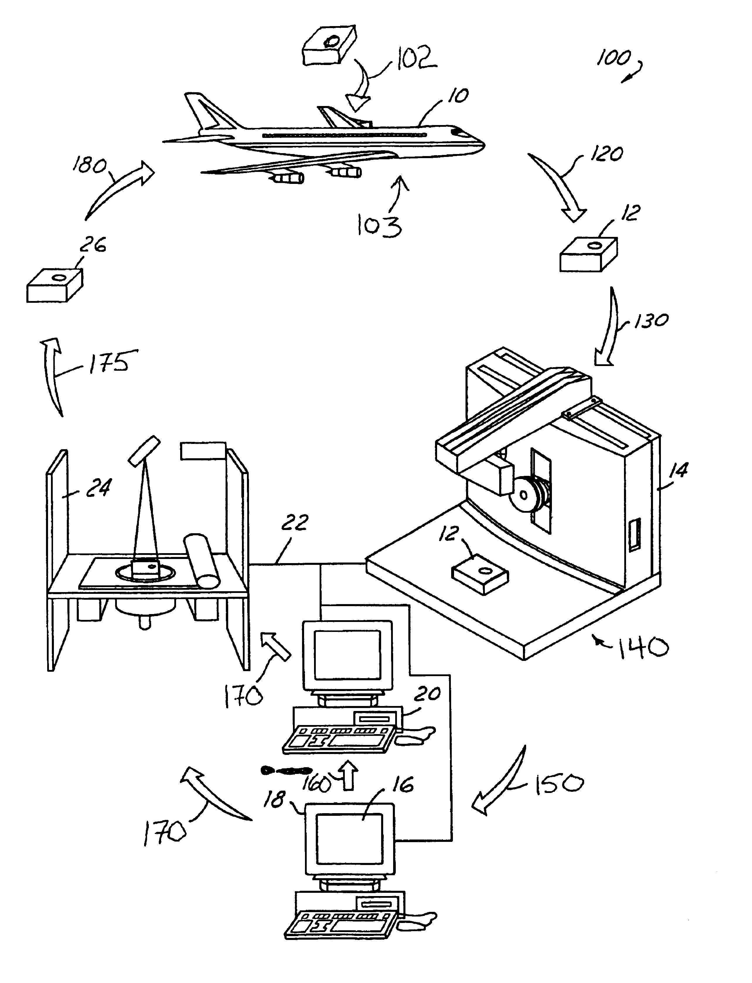
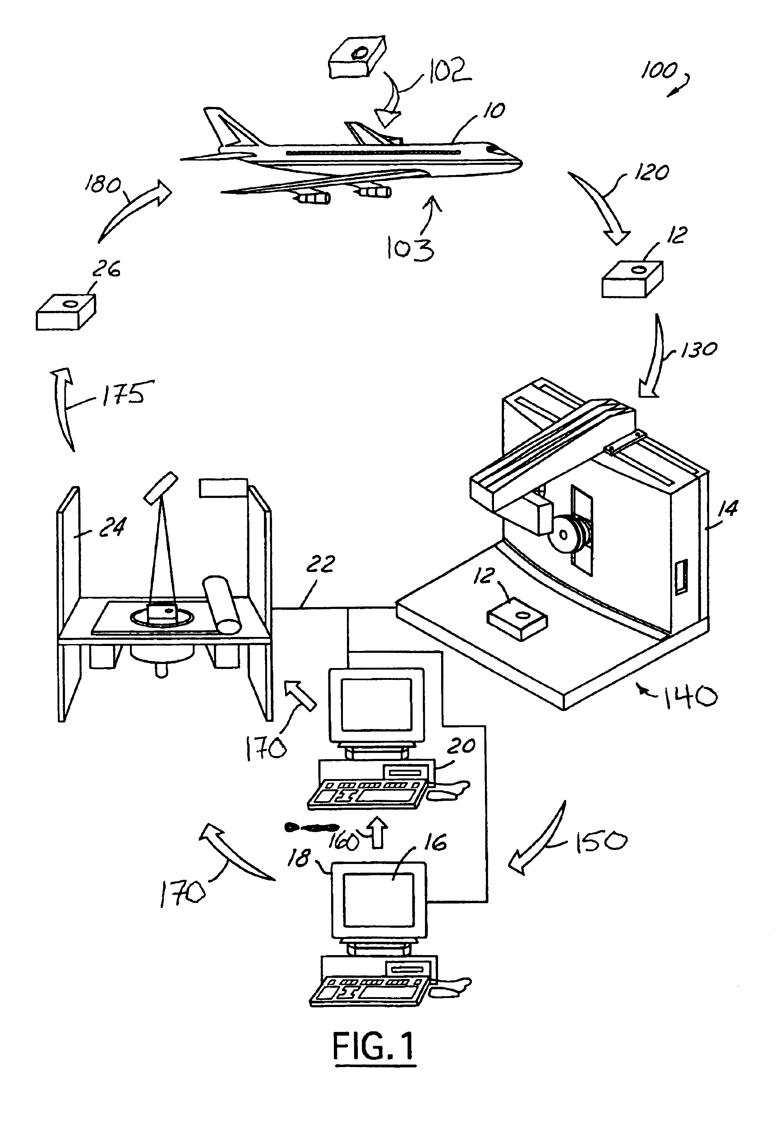
In accordance with the objects of the present invention a method for the rapid manufacturing of aerospace replacement parts is provided. The method includes removing an in-service aerospace part from an aerospace system. The in-service aerospace part is placed into a three-dimensional scanning device. The present invention further includes scanning the in-service aerospace part. The present invention then develops a computer-aided-design model based on the three-dimensional scan. The present invention finally includes direct metal fabricating a replacement part from the computer-aided-design model utilizing a layer-build technology device.

Problems solved by technology

Aerospace and military applications often provide unique challenges to design and manufacturing.
The nature of these applications often requires limited run and small-lot productions that result in high cost because of the small quantity of individualized assemblies.
Part cost can be extremely expensive due to the cost of tooling and long lead-time associated with developing and fabricating the tooling.
Additionally, the parts “as designed” may not in fact interface correctly into the existing systems.
When this situation arises, a complete redesign of part layout and tooling may be required at considerable expense.
In addition, where original tooling is no longer available, redevelopment and fabrication of tooling is often required.
This can result in undesirable costs associate with supply of the replacement parts.
This, however, can result in large inventory costs that counter the cost savings associated with the larger production runs.

Method used


Image

  • System for rapid manufacturing of replacement aerospace parts
  • System for rapid manufacturing of replacement aerospace parts

Examples


Embodiment Construction

Referring now to FIG. 1, which is an illustration of a method 100 for the rapid manufacturing of aerospace replacement parts in accordance with the present invention. The method 100 includes removing 120 an in-service aerospace part from an aerospace system. It is contemplated that the aerospace system 10 can encompass a wide variety of aircraft and military applications. Similarly the in-service aerospace part 12 is intended to encompass any number of components within the aircraft 10. Although a variety of in-service aerospace parts 12 are contemplated, one embodiment contemplates the removal of metal components from the aircraft. The nature of many in-service aerospace parts 12 within an aircraft 10 is such that after continuous use within the aerospace system 10 they can become worn or adapt to their surroundings. Thus the aerospace system 10 as a whole can adjust to the point that parts as originally designed may not fit or properly function. Thereby inserting 102 a part into t...


PUM


Abstract

An method for the rapid manufacturing of aerospace replacement parts 100 is provided, including removing an in-service aerospace part from an aerospace system 120. The present invention further includes placing the in-service aerospace part into a three-dimensional scanning device 130. The invention then scans the in-service aerospace part utilizing the three-dimensional scanning device to develop a three-dimensional scan 140. A computer-aided-design model is then developed based on the three-dimensional scan 150. The invention then direct metal fabricates a replacement aerospace part from the computer-aided-design model utilizing layer-build technology device 170. Finally the replacement aerospace part is installed back into the aerospace system 180.

Description

TECHNICAL FIELDThe present invention relates generally to an apparatus and method for the rapid manufacturing of replacement parts for aging systems, such as, for aerospace or military applications, and more particularly to an apparatus and method for the manufacturing of small-lot aerospace and military grade replacement parts without the cost and extensive lead-time associated with the development and manufacturing of tooling.BACKGROUND OF THE INVENTIONAerospace and military applications often provide unique challenges to design and manufacturing. The nature of these applications often requires limited run and small-lot productions that result in high cost because of the small quantity of individualized assemblies. Part cost can be extremely expensive due to the cost of tooling and long lead-time associated with developing and fabricating the tooling. If these costs are associated with initial build, they are even more prevalent in dealing with replacement parts for aging aircraft...

Claims


Application Information

Patent Timeline
IPC IPC(8): B64F5/00G05B19/42G05B19/4097G05B19/4099B29C67/00
CPCB64F5/0009G05B19/4207G05B19/4099B29C67/0051G05B2219/49008B33Y50/00B33Y80/00B64F5/10Y02P90/02
Inventor WOOTEN, JOHN R.
Owner THE BOEING CO
Learn More