System and method for determining oil grade

a technology of oil grade and system, applied in the direction of machines/engines, electrical control, instruments, etc., can solve the problems of affecting engine performance and reducing engine performan

Inactive Publication Date: 2005-01-11
CATERPILLAR INC
View PDF12 Cites 52 Cited by
  • Summary
  • Abstract
  • Description
  • Claims
  • Application Information

AI Technical Summary

Benefits of technology

In a second embodiment, a system for determining oil grade comprises a temperature sensor, a pressure sensor, and an electronic control module connected to the temperature sensor and pressur...

Problems solved by technology

Although lubrication oil is a preferred actuation fluid in engine systems, it does have some drawbacks.
The viscosity of the oil can impact the timing of the desired actuation event which, in t...

Method used


Image

  • System and method for determining oil grade
  • System and method for determining oil grade

Examples


Embodiment Construction

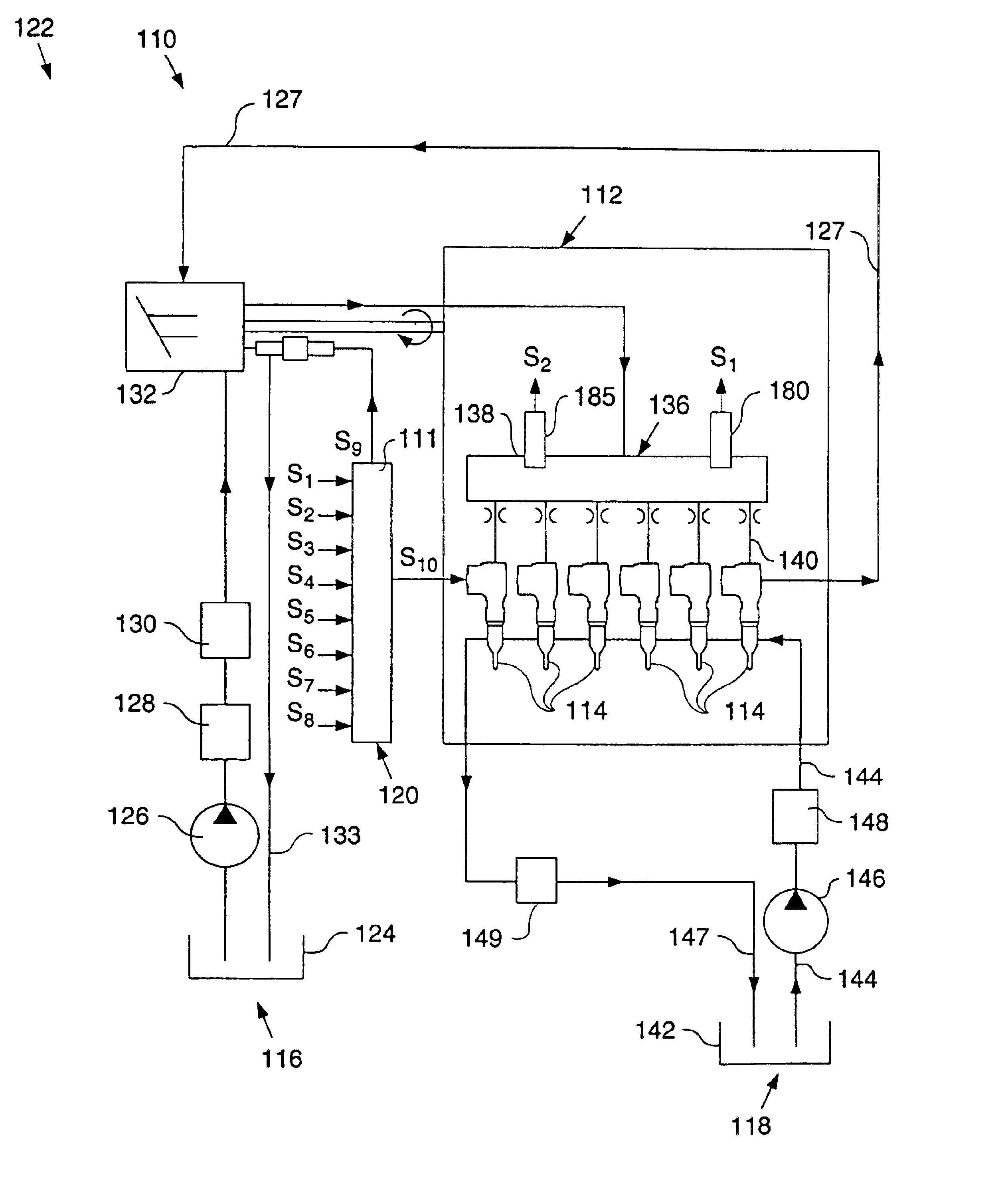
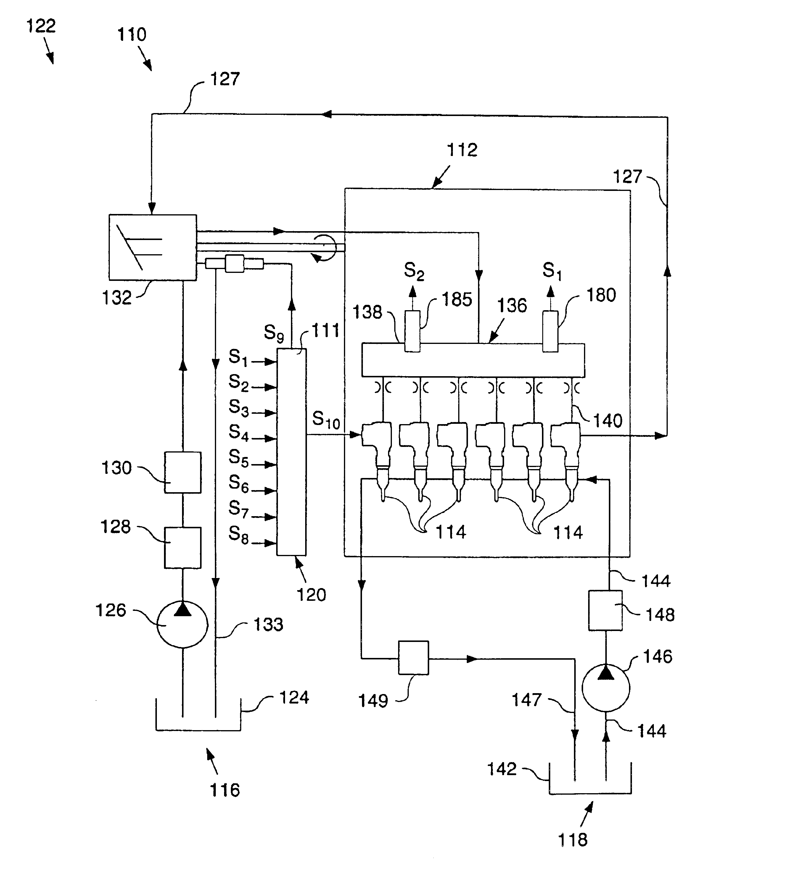
FIG. 1 illustrates an embodiment of a hydraulically actuated electronically controlled fuel injection system 110 in an example configuration as adapted for a direct-injection diesel-cycle internal combustion engine 112. Fuel system 110 includes one or more hydraulically-actuated electronically-controlled fuel injectors 114, positioned in a respective cylinder head bore (not shown) of engine 112. Fuel system 110 includes a first source of pressurized fluid flow 116 for supply of actuating fluid to each injector 114, a second source of pressurized fluid flow 118 for supplying fuel to each injector, a computer 120 for electronically controlling the fuel injection system and an apparatus 122 for re-circulating actuation fluid leaving each of the injectors.

The first fluid source 116 preferably includes an actuating fluid sump 124, a relatively low pressure actuating fluid transfer pump 126, an actuating fluid cooler 128, one or more actuation fluid filters 130, a high pressure pump 132 f...


PUM


Abstract

The grade of oil used in a machine or apparatus can be determined by determining a temperature and pressure within an oil supply and determining the oil grade in response to determining the temperature and pressure.

Description

TECHNICAL FIELDThe present invention relates to determining the grade of oil used in a machine or apparatus.BACKGROUNDOil is used in numerous applications and is commonly used as a lubricant in engines. Due to the broad range of engines and operating environments, lubrication oil is available in a variety of different viscosities (formulations, weights, or grades). For example, lubrication oil could be a single viscosity oil, such as SAE 30 base oil, which has a viscosity of 30 at a set testing temperature or lubrication oil could be a multi-viscosity oil, such as 15W40, 0W30, or 10W30. With multi-viscosity oils, the first number indicates a first viscosity at a first temperature (a cold temp.) and the second number indicates the oil's second viscosity at a second temperature (a hot temp.) Multi-viscosity oils are beneficial in engine use to help handle the diverse operating environments, such as cold start.In some devices or engine systems, lubrication oil is also used as an actuat...

Claims


Application Information

Patent Timeline
IPC IPC(8): F02M59/10F01M11/10F02M57/00F02M57/02F02M59/00F02D41/38G01N11/00G01N33/28G01N33/26G01N11/08
CPCF01M11/10F02D41/3809F02M57/025G01N11/08G01N33/2888F02M59/105G01N2011/0013
Inventor KASEN, JON E.LEE, MICHELLE A.
Owner CATERPILLAR INC
Why Eureka
Try Eureka