
Reduced Carbon Footprint Steam Generation Processes

Active Publication Date: 2009-09-03
SURE CHAMPION INVESTMENT LTD
View PDF100 Cites 113 Cited by
  • Summary
  • Abstract
  • Description
  • Claims
  • Application Information

AI Technical Summary

Benefits of technology

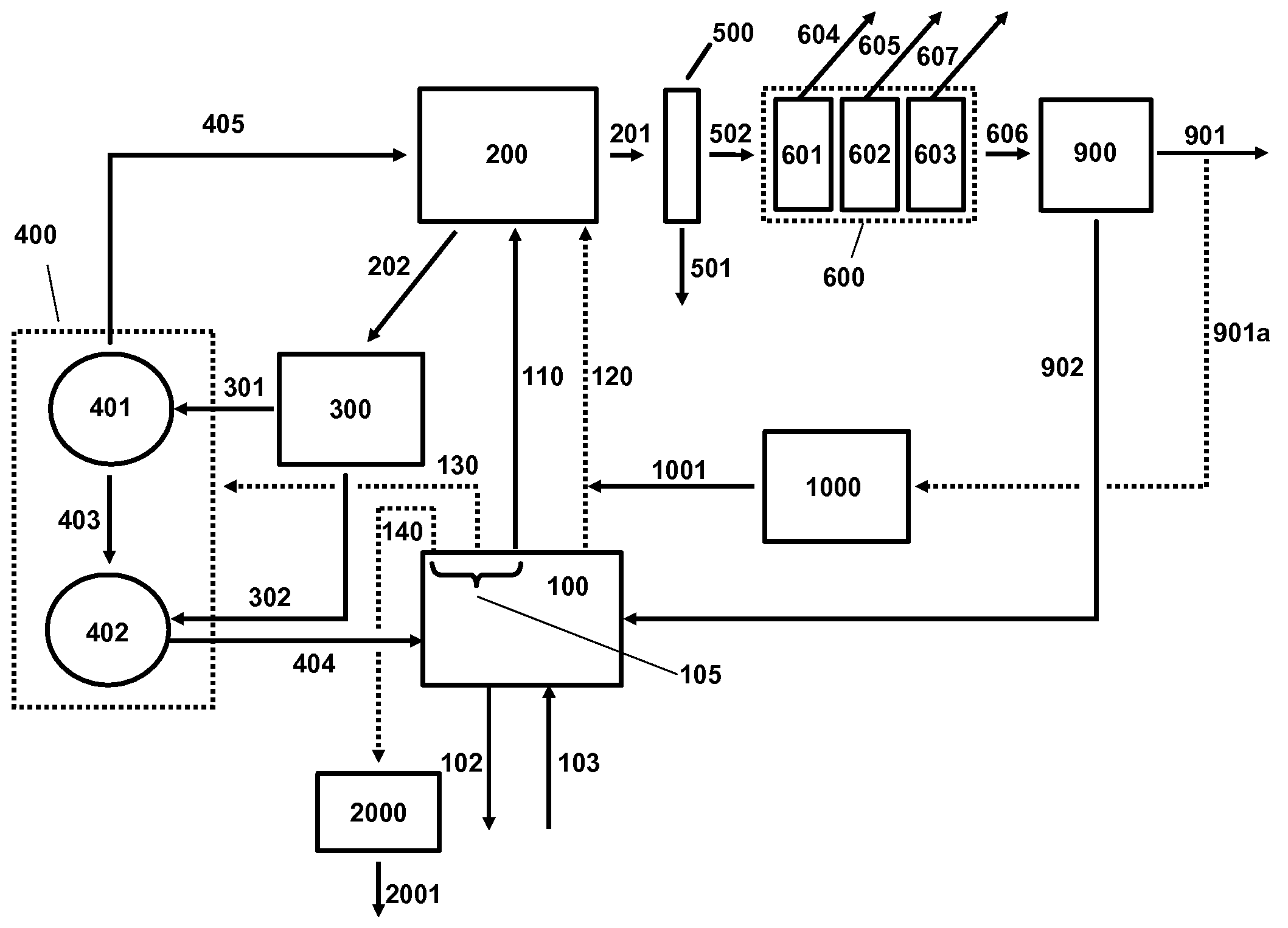
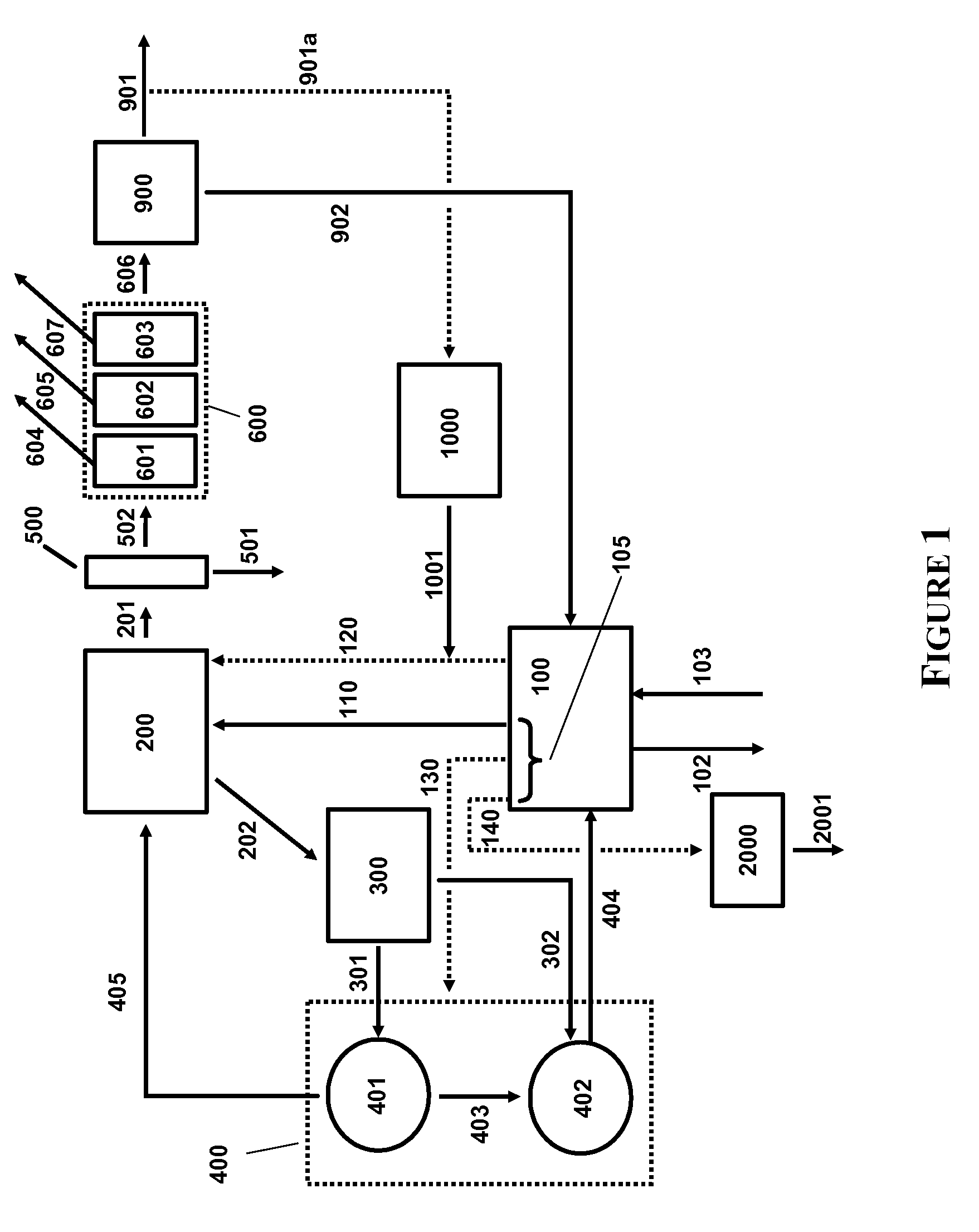
[0005]In a first aspect, the present invention provides a process for generating steam and a plurality of gaseous products from a carbonaceous feedstock and recovering carbon dioxide, the process comprising the steps of: (a) supplying a first carbonaceous feedstock to a reactor, the reactor in communication with a gasifier; (b) at least partially combusting the first carbonaceous feedstock in the reactor to generate (i) heat energy and (ii) a first gas stream comprising carbon dioxide; (c) utilizing the heat energy to generate steam; (d) introducing at least a portion of the steam, the first gas stream, a second carbonaceous feedstock, and an alkali metal gasification catalyst to the gasifier; (e) reacting the second carbonaceous feedstock in the gasifier in the presence of the steam and the alkali metal gasification catalyst and under suitable temperature and pressure to form a second gas stream comprising a plurality of gaseous products comprising methane, carbon dioxide and at least one or more of hydrogen, carbon monoxide, hydrogen sulfide, ammonia and other higher hydrocarbons; (f) at least partially separating the plurality of gaseous products to produce (i) a third gas stream comprising carbon dioxide and (ii) a fourth gas stream comprising a predominant amount of one of the gaseous products other than carbon dioxide; (g) recovering the third gas stream; and (h) recovering the fourth gas stream, wherein the third gas stream includes carbon dioxide formed in steps (b) and (e).
[0006]In a second aspect, the present invention provides a process for generating steam,

Problems solved by technology

Such methods have the disadvantages of requiring an additional fuel source for the boiler, while producing an exhaust comprising carbon dioxide, which is either exhausted to the atmosphere or otherwise sequestered.

Method used


Image

  • Reduced Carbon Footprint Steam Generation Processes
  • Reduced Carbon Footprint Steam Generation Processes

Examples


example 1

Catalyzed and Slurry Feedstock Preparation

[0085]As-received coal (Powder River Basin) can be stage-crushed to maximize the amount of material having particle sizes ranging from about 0.85 to about 1.4 mm. Fines (<0.85 mm) are separated from the crushed materials by vibratory screening and directed to the steam generating combustion reactor.

[0086]The crushed coal would be slurried with an aqueous solution of potassium carbonate, dewatered, and dried via a fluid bed slurry drier to typically yield a catalyzed feedstock containing 185 lb coal (88 wt %), 14.9 lb catalyst (7 wt %), and 10.5 lb moisture (5 wt %). The coal fines separated at the crushing stage can be used as the feedstock for combustion reactor for the preparation of steam.

example 2

Catalytic Gasification

[0087]The fines of Example 1 can be provided to a combustion reactor fed by an enriched oxygen source. The resulting exhaust gas from the combustion reactor would contain hot CO2. The exhaust gas can be passed through a heat exchange in contact with a water source to produce steam. The generated steam and the exhaust gas from the combustion reactor can be superheated and then introduced to a fluidized bed gasification reactor (catalytic gasifier) supplied with the catalyzed feedstock of Example 1. The catalyzed feedstock is introduced under a positive pressure of nitrogen. Typical conditions for the catalytic gasifier would be: total pressure, 500 psi and temperature, 1200° F. The effluent of the catalytic gasifier would contain methane, CO2, H2, CO, water, H2S, ammonia, and nitrogen, which is passed to a scrubber to remove ammonia and an acid gas removal unit to remove H2S and CO2. The CO2 can then be recovered.


PUM


Abstract

Processes for the generation of steam are provided for use in an integrated catalytic gasification process for converting carbonaceous materials to combustible gases, such as methane. Generally, the exhaust gas from a steam generating reactor is provided along with steam, a carbonaceous feedstock, and a gasification catalyst, to a catalytic gasifier, wherein under appropriate temperature and pressure conditions, the carbonaceous feedstock is converted into a plurality of product gases, including, but not limited to, methane, carbon monoxide, hydrogen, and carbon dioxide. As substantially all the carbon dioxide produced from the steam generation process and the gasification process are subsequently directed though gas purification and separation processes, substantially all the carbon dioxide may be recovered, yielding a process having a near zero carbon footprint.

Description

CROSS-REFERENCE TO RELATED APPLICATIONS[0001]This application claims priority under 35 U.S.C. §119 from U.S. Provisional Application Ser. No. 61 / 032,736 (filed Feb. 29, 2008), the disclosure of which is incorporated by reference herein for all purposes as if fully set forth.FIELD OF THE INVENTION[0002]The present invention relates to methods for the production of steam for a catalytic gasification reactor which have a reduced carbon footprint.BACKGROUND OF THE INVENTION[0003]In view of numerous factors such as higher energy prices and environmental concerns, the production of value-added gaseous products from lower-fuel-value carbonaceous feedstocks, such as biomass, coal and petroleum coke, is receiving renewed attention. The catalytic gasification of such materials to produce methane and other value-added gases is disclosed, for example, in U.S. Pat. No. 3,828,474, U.S. Pat. No. 3,998,607, U.S. Pat. No. 4,057,512, U.S. Pat. No. 4,092,125, U.S. Pat. No. 4,094,650, U.S. Pat. No. 4,2...

Claims


Application Information

Patent Timeline
IPC IPC(8): C10L3/00C01B32/40C01B32/50
CPCC10J3/00Y02E20/18C10J2300/0969C10J2300/0973C10J2300/0986C10J2300/1606C10J2300/1662C10J2300/1671C10J2300/1675C10J2300/1687C10J2300/1807C10J2300/1823C10J2300/1853C10J2300/1892C10L3/08F01K23/068C10J2300/0916Y02P20/145
Inventor RAMAN, PATTABHI K.LAU, FRANCIS S.ROBINSON, EARL T.ANTHONY, DONALD
Owner SURE CHAMPION INVESTMENT LTD
Learn More