Method and apparatus for monitoring a controllable valve

a controllable valve and operation status technology, applied in the direction of electric control, instruments, combustion-air/fuel-air treatment, etc., can solve the problem of reducing the accuracy of such measurements, and achieve the effect of simplifying diagnosis

Inactive Publication Date: 2005-01-11
FORD GLOBAL TECH LLC
View PDF9 Cites 20 Cited by
  • Summary
  • Abstract
  • Description
  • Claims
  • Application Information

AI Technical Summary

Benefits of technology

According to the invention, the mechanical function of a cyclically operated valve is monitored by existing sensors in an arrangement. The invention both simplifies the diagnosis and ensures proper function of the valve in a cost effective way, as an available signal is processed by the diagnostics system.

Problems solved by technology

However, the accuracy of such measurements is reduced due to the low signal to noise ratio in the output signal from the pressure sensor.

Method used


Image

  • Method and apparatus for monitoring a controllable valve
  • Method and apparatus for monitoring a controllable valve
  • Method and apparatus for monitoring a controllable valve

Examples


Embodiment Construction

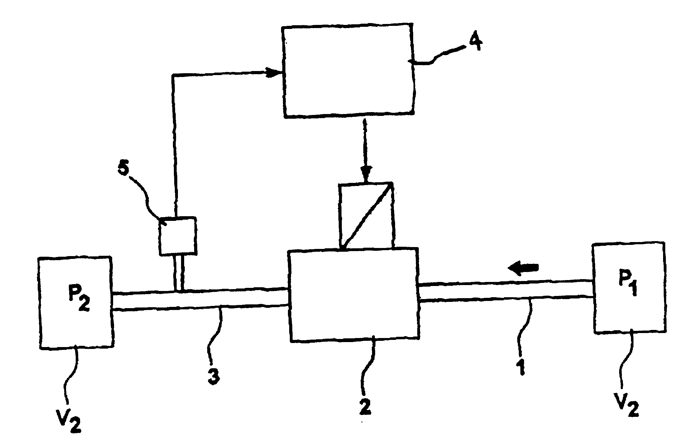
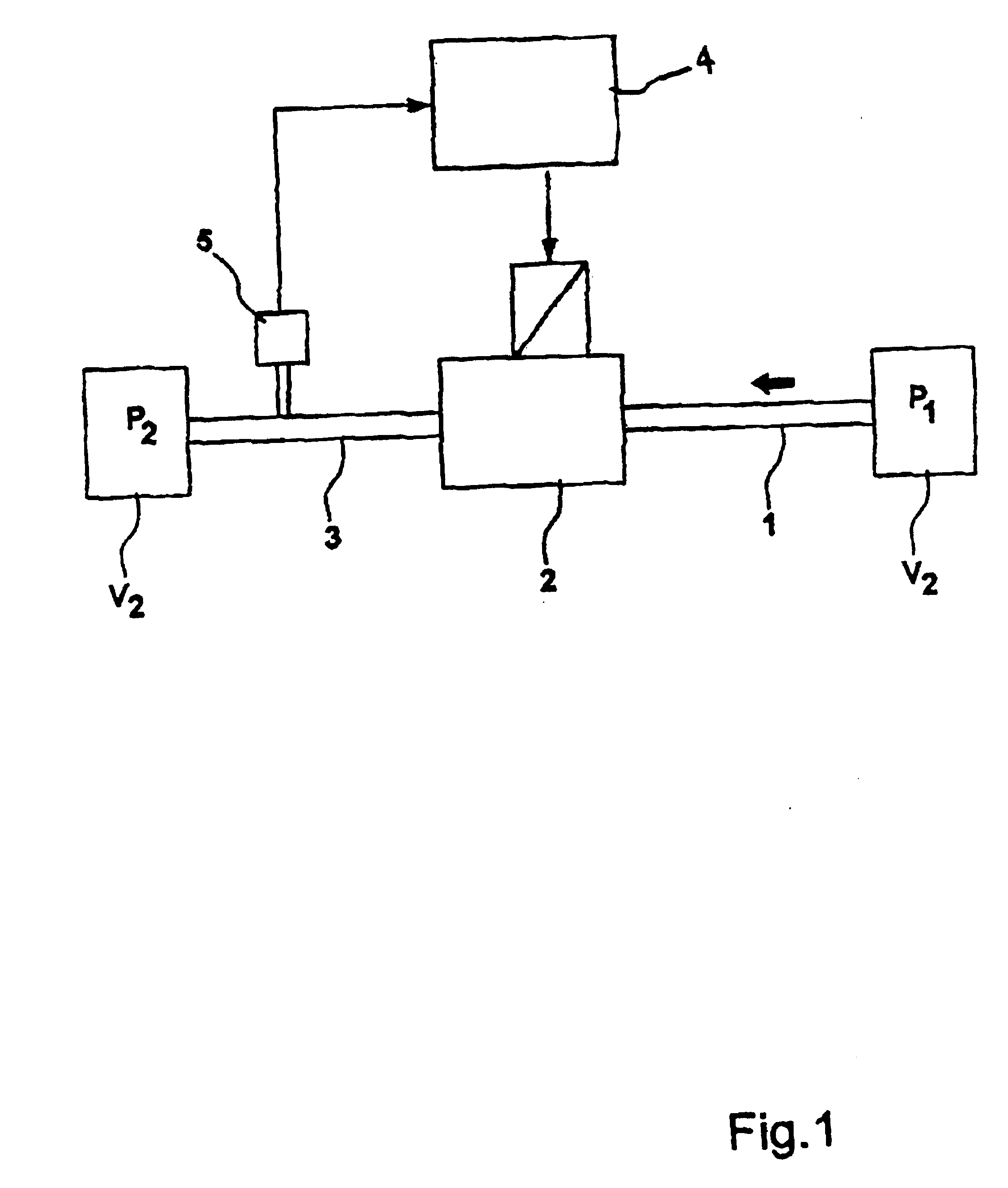
FIG. 1 shows a schematic diagram of one embodiment of the invention including a first conduit 1, an electronically operated valve 2 and a second conduit 3. A fluid or gaseous medium is arranged to flow into the first conduit 1, through the valve 2 and out of the second conduit 3, whenever the valve 2 is opened. The gaseous medium can be a gas or a vapor and is hereinafter termed “gas”, while the fluid may be any type of flowing liquid. The source of the fluid or gas is a first volume V1 located upstream of the first conduit 1, while a second volume V2 is located downstream of the second conduit 3 for receiving said fluid or gas. The valve is arranged to open only when the pressure P1 in the first volume exceeds the pressure P2 in the second volume V2. This is monitored by an electronic control unit (ECU) 4, which uses the output signal from a pressure sensor 5 placed downstream of the valve 2 in combination with a number of known conditions relating to the first and second volumes. ...


PUM


Abstract

The invention relates to a method and an arrangement for monitoring the operational status of a cyclically operated valve (5, 19), which valve is operated to allow a fluid or gaseous medium to flow from a first conduit (1, 18) to a second conduit (3, 20) due to a pressure difference between said conduits, whereby the valve (5, 19) operated using predetermined duty cycles. The method involves measuring pressure oscillations caused by the valve (5, 19) and generating an output signal, performing a frequency analysis on the signal to determine an amplitude for the signal at an oscillation frequency, comparing the amplitude of the oscillations to an expected amplitude for the oscillation frequency, and generating an error signal is if the difference between the calculated and the expected amplitudes exceeds a predetermined limit.

Description

FIELD OF THE INVENTIONThe present invention relates to a method and an apparatus for monitoring the operational status of a controllable valve arranged to regulate a fluid or gaseous flow.BACKGROUNDCyclically operated or oscillating valves for regulating the flow of a fluid or gaseous medium are used in many applications. To ensure proper operation of a device or a process, it is desirable to monitor the mechanical function of such valves. By monitoring the valve or valves, it is possible to limit or prevent the occurrence of breakdowns and / or emissions caused by valve failure.In general, vehicles are provided with a purge system to prevent fuel evaporated in a fuel tank from being discharged into the atmosphere. Instead, the evaporated fuel is absorbed in a canister containing activated carbon, which canister is placed in a conduit connecting the fuel tank and the intake pipe of the engine. The fuel absorbed by the canister over a period of time is released to the engine by a contr...

Claims


Application Information

Patent Timeline
Patent Type & Authority Patents(United States)
IPC IPC(8): F02M25/08
CPCF02M25/0809F02D2041/288F02M25/0836
Inventor LINGENHULT, ANDERSSANDBERG, ERIK
Owner FORD GLOBAL TECH LLC
Why Eureka
Try Eureka