Flexible tubular pipe

Inactive Publication Date: 2005-01-11
COFLEXIP +1
View PDF11 Cites 49 Cited by
  • Summary
  • Abstract
  • Description
  • Claims
  • Application Information

AI Technical Summary

Benefits of technology

One advantage of the present invention lies in the fact that use is made of a metal strip which is not very costly and lends itself well to being bent in order to form separate box sections and thus to realize a profile which has a high moment of inertia, while still maintaining a high moment of inertia/weight ratio when the prof

Problems solved by technology

Such a shaped wire has an acceptable moment of inertia/weight ratio but the manufacturing cost is very high because of the fact that it is obtained by rolling or wire drawing.
This is because if the profile is too wide, during winding the forces will be too high and there would be a risk of melting the side walls of the profile buckle.
Although such box-section profiled strips have been satisfactory, they have been found to have certain drawbacks.
However, such a solution increases the manufacturing cost and it is difficult to implement.
However, the welding operation is difficult to implement and considerably increases the manufacturing cost.
This may result in a local fracture of the weld.
Such a fracture of the weld may, in turn, result in a considerable reduction in th

Method used


Image

  • Flexible tubular pipe
  • Flexible tubular pipe
  • Flexible tubular pipe

Examples


Embodiment Construction

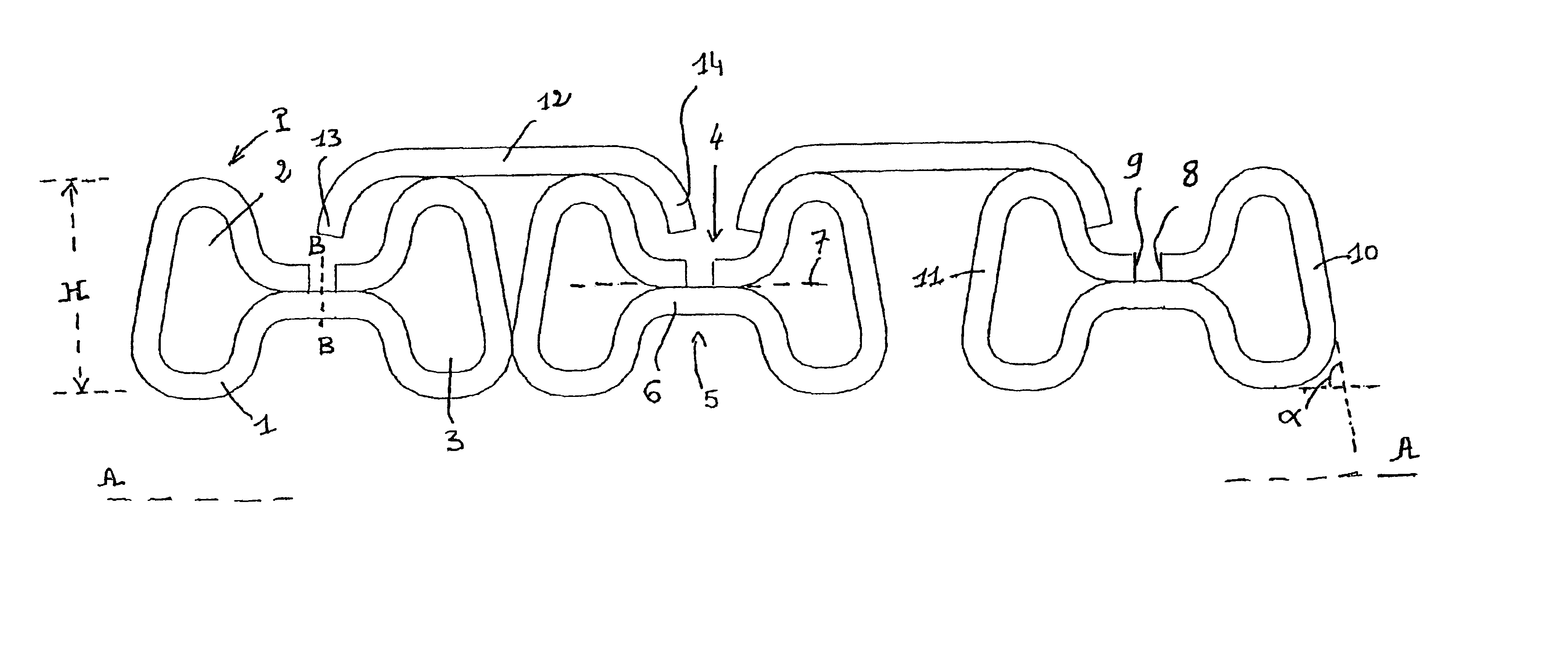
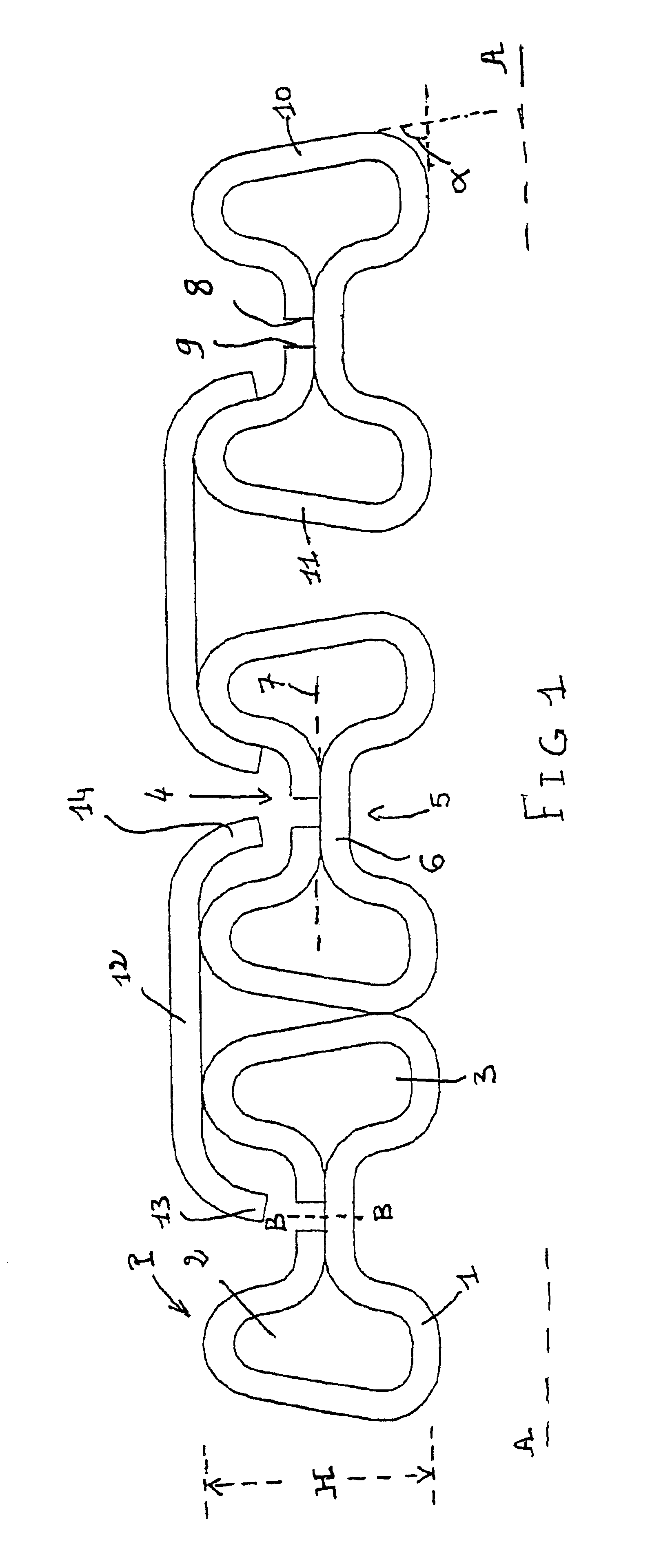
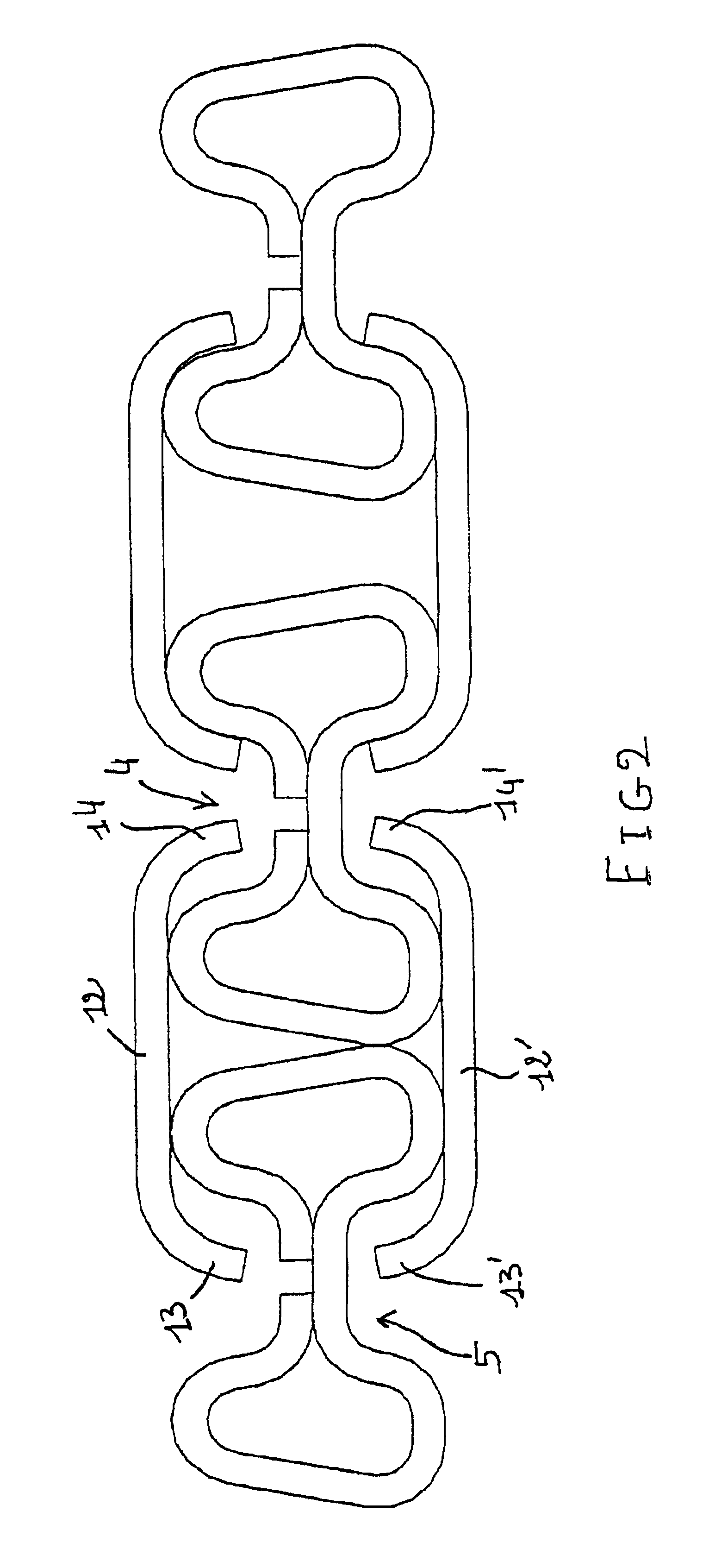
The profile P according to the invention shown in FIGS. 1 and 2 consists of a metal strip 1 which is bent so as to form two separate trapezoidal box sections 2, 3 which are symmetrical with respect to a vertical axis of symmetry B—B. The box sections 2, 3 are separated by a radially inwardly projecting upper bulge 4 and a radially outwardly projecting lower bulge 5. The strip portion 6 which constitutes the bottom of the lower bulge 5 lies approximately in the plane of the neutral fibre 7 (at the radial position where it is neither compressed nor stretched during winding) and the free edges 8, 9 of the strip which have been turned down inwards during the bending bear on said strip portion 6, with the free edges 8, 9 being aligned and placed opposite each other, as shown in the figures.

Each trapezoidal box section 2, 3 has side walls 10, 11 which are inclined and make an angle cc greater than 60° and less than 90° with the horizontal C so that, owing to the effect of the contact pres...


PUM


Abstract

A flexible tubular pipe comprising at least one metal profile spiralled in a helix about a longitudinal axis of the flexible pipe. The profile consists of a metal strip, each turn of which comprises two separate box sections which are obtained by bending the said strip so that the free edges of the strip are turned down between the two box sections and are in contact with a strip portion provided on an upraised bulge formed between the two box sections. The contact portion ties approximately along the neutral fiber of the profile. Each box section has a trapezoidal shape. Connectors above or below the profile connect windings. The edges of the connectors extend into the bulges. Profiling or extra elements are provided for the connectors.

Description

BACKGROUND OF THE INVENTIONThe present invention relates to a flexible tubular pipe which can be preferably used in deep-sea applications, for depths of between 1000 and 3000 m, although it can also be used for depths of less than 1000 m. Such flexible tubular pipes are used in subsea oil production installations for transporting fluids such as hydrocarbons.Several types of flexible tubular pipes are used at the present time and are described in API (American Petroleum Institute) 17 J. In certain flexible pipes, there is a pressure vault which consists of a helical winding with a short pitch of a shape to wire which may be self-interlockable or interlockable by means of a fastener. Likewise, the metal carcasses used in flexible pipes called “rough bores” are formed from a crush-resistant doubly interlocking profiled metal strip.In all cases, it has been attempted to improve the moment of inertia / weight ratio of the interlocked strips or shaped wires used for producing the various me...

Claims


Application Information

Patent Timeline
IPC IPC(8): F16L11/16F16L11/00F16L11/24F16L11/08
CPCF16L11/083F16L11/24F16L11/16
Inventor ESPINASSE, PHILIPPEJUNG, PATRICE JOEL LOUIS
Owner COFLEXIP
Why Eureka
Try Eureka