Device for holding a badge and an identification card

a technology for holding a badge and an identification card, applied in the field of badges, can solve the problems of counterfeit badges, undesirable pining of badges on exterior layers of clothing, and difficulty in obtaining counterfeit badges, and achieve the effect of convenient use and low manufacturing cos

Inactive Publication Date: 2005-01-11
HUDSON ALFRED R
View PDF20 Cites 33 Cited by
  • Summary
  • Abstract
  • Description
  • Claims
  • Application Information

AI Technical Summary

Benefits of technology

It is yet still another object of the present invention to provide a device as described above which has a limited number of parts, which is inexpensive to manufacture and is easy to use.

Problems solved by technology

Pinning a badge onto an exterior layer of clothing has been found to be undesirable.
Although well-known and widely used in commerce, conventional badge holders typically suffer from a notable drawback.
Specifically, it has been found that people, on occasion, manufacture counterfeit badges or unlawfully acquire an authentic badge.
As can be appreciated, the ability of unauthorized people to represent themselves as legitimate officers poses a significant safety threat.
Requiring an officer to provide an identification card in addition to a badge introduces a notable drawback.
As a result, when required to display an identification card, an officer must reach inside his / her pocket to withdraw the identification card, which can be considerably cumbersome, time-consuming and / or dangerous (e.g., when an officer is using both hands to restrain someone).

Method used


Image

  • Device for holding a badge and an identification card
  • Device for holding a badge and an identification card
  • Device for holding a badge and an identification card

Examples


first embodiment

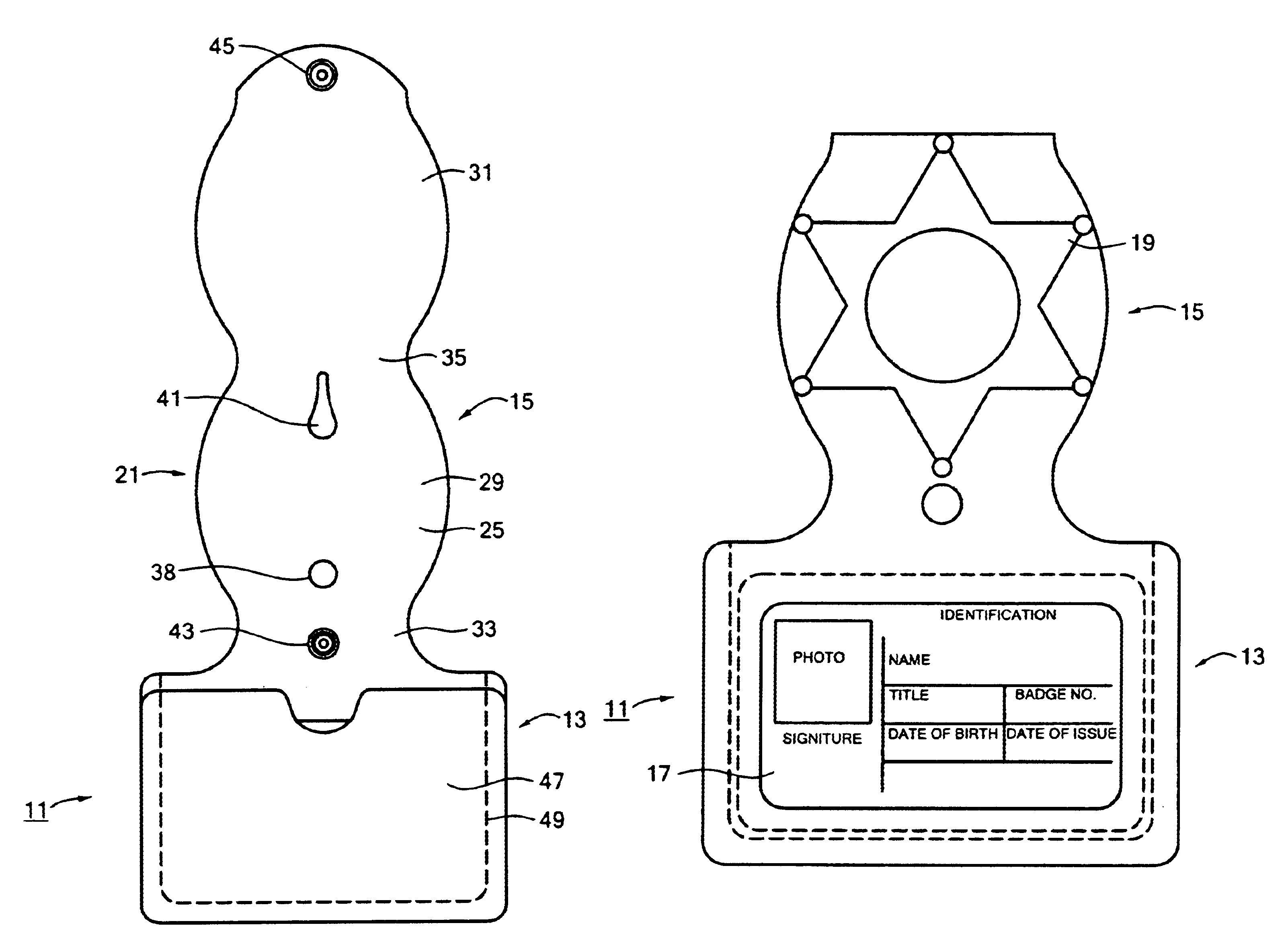
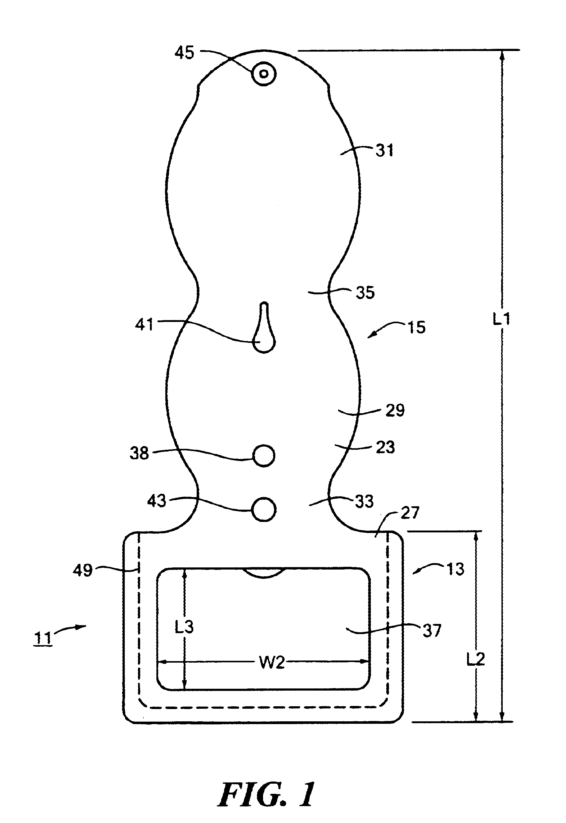
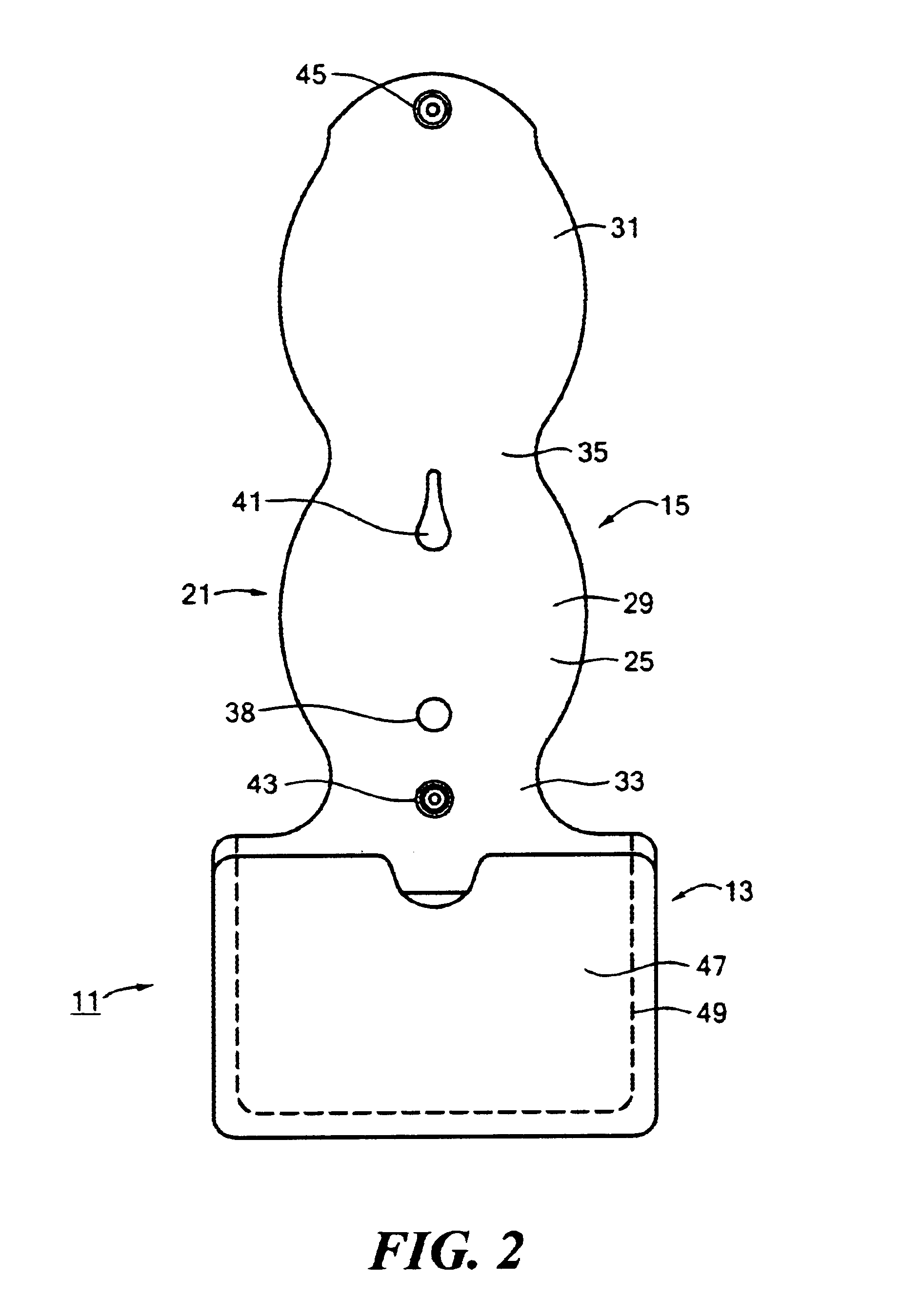
Referring now to FIGS. 1-5, there is shown device for holding a badge and an identification card, the device being constructed according to the teachings of the present invention and identified generally by reference numeral 11.

Device 11 comprises a first section 13 and a second section 15. As seen most clearly in FIG. 3, first section 13 is adapted to retain a conventional identification (ID) card 17. Second section 15 is adapted to retain a conventional badge 19. As will be described further in detail below, second section 15 can also be releasably formed into a closed loop. In this capacity, device 11 can be easily mounted onto a belt B in such a manner so as to readily display identification card 17 and badge 19 in plain view of others, which is a principal feature of the present invention.

As seen most clearly in FIGS. 1 and 2, device 11 comprises an elongated, flattened, unitary strip of material 21. For aesthetic and durability purposes, strip of material 21 is preferably manu...

second embodiment

Referring now to FIG. 6, there is shown a device for holding a badge and an identification card, the device being constructed according to the teachings of the present invention and identified generally by reference numeral 101.

Device 101 differs from device 11 in two principal ways. First, device 101 comprises a strip of material 121 which differs slightly in shape from strip of material 21. Second, device 101 additionally comprises a conventional spring clip 123.

With regard to the first difference, strip of material 121 is shaped to include an enlarged rectangular portion 127, a first enlarged oval portion 129, a second enlarged oval portion 131, a neck 133 of reduced width for connecting portion 127 to portion 129, and a neck 135 of reduced width for connection portion 129 to portion 131. Strip of material 121 differs from strip of material 21 only in that portion 131 of strip of material 121 is shaped to include a first opening 137 and a second opening 139, first opening 137 bei...


PUM


Abstract

A device for holding a badge and an identification card includes a first strip of material constructed of leather. The first strip of material is shaped to include first and second generally oval-shaped portions which are connected through a neck. The first portion is shaped to include a pair of openings through which the badge can be pinned. A second strip of material constructed of leather is sewn onto the first strip of material along three sides so as to define a generally rectangular-shaped pocket for receiving the identification card, the first strip of material being shaped to include a centered window to display the identification card when disposed within the pocket. The first strip of material can be folded about the neck to form a closed loop. A pair of complementary fasteners are mounted onto the first strip of material to retain the device in its closed loop configuration.

Description

BACKGROUND OF THE INVENTIONThe present invention relates generally to badges and more particularly to badge holding devices.An officer (e.g., a police officer or a corrections officer) is typically issued a badge as a means to authenticate his / her position of employment. The badge of an officer is typically manufactured of metal in an ornamental design (e.g., a star) with the title of the officer displayed thereon.An officer often wears his / her badge in plain view in order to readily provide others with the proper identification of the position of the officer. Specifically, a fastening device is typically mounted onto the rear surface of the badge which, in turn, enables the badge to be removably mounted onto an exterior layer of the officer's clothing, such as a jacket. The fastening device is commonly in the form of an elongated sharpened pin which is pivotally mounted onto the back surface of the badge, the elongated sharpened pin being releasably retained in place by a clasp whi...

Claims


Application Information

Patent Timeline
Patent Type & Authority Patents(United States)
IPC IPC(8): A44C3/00G09F3/08G09F3/20A45F5/02
CPCA44C3/001G09F3/207A45F5/021A45F5/02A45C11/18A45C11/182A45F2200/055
Inventor HUDSON, ALFRED R.
Owner HUDSON ALFRED R
Why Eureka
Try Eureka