Automatic printhead-to-media spacing adjustment system

a technology of automatic adjustment and printhead, applied in the direction of printing mechanism, printing, power drive mechanism, etc., can solve the problems of affecting the quality of printheads, affecting the output quality, and obtaining disappointing outputs, etc., to achieve high quality

Inactive Publication Date: 2005-01-11
HEWLETT PACKARD DEV CO LP
View PDF9 Cites 12 Cited by
  • Summary
  • Abstract
  • Description
  • Claims
  • Application Information

AI Technical Summary

Benefits of technology

Normally to improve printing speed, known as “throughput” measured in pages per minute, print quality is unfortunately sacrificed. Tests have shown that faster print speeds may be obtained, along with higher print quality, if the PPS spacing is reduced. One of the main stopping blocks to reducing PPS spacing lower than current levels is that envelopes, as well as other thicker print media, do not feed well through a nominal plain paper PPS spacing without smearing against the printheads. Thus, it would be desirable to have an automatic way to switch between two different printhead to platen separations, a large one for thicker media and small one for regular plain paper media, as well as transparencies, premium papers, and photo media.
Indeed, it would be desirable to provide more than two different PPS spacings to accommodate different types of specialty media. For example, plain papers often swell during printing as they soak up the liquid from the ink composition, a problem in the art often referred to as “cockle” where the media actually begins to buckle. Thus, for printing on plain papers the PPS spacing must be larger to avoid printhead crashes into upwardly bowed portions of the paper. In contrast, when printing upon various premium and photo medias, including transparencies, typically very little ink is absorbed into the media, so cockle is not a problem, allowing closer PPS spacings to be used. Closer PPS spacings are typically associated with yielding higher print quality, so in printing upon these specialty medias which are immune to cockle, it would be desirable to have a closer PPS spacing than when printing on plain paper. Indeed, as the various types of print media change, with different swelling characteristics and thicknesses, a variety of different spacings between the media support platen and the printhead may be desirable to accommodate these varying different thicknesses and cockle characteristics. Furthermore, as mentioned above it would be desirable to have this adjustment be accomplished without user intervention to provide a more robust, and easier to use printing mechanism, which continuously provides high print quality on a variety of different types of media.

Problems solved by technology

Thicker media decreases the spacing from the printhead to the printing surface, and in the worst case, this reduced spacing could lead to contact of the printhead with the media, known as a “printhead crash,” possibly damaging either the printhead or the image.
Unfortunately, one danger in ignoring printhead to paper spacing was the potential for suffering a printhead crash.
Unfortunately, in these user switchable systems, most users either never understood the switch, or never knew the switch existed, and if they did, they rarely if ever used it, so they continually obtained disappointing outputs when switching between different thicknesses of media.
One of the main stopping blocks to reducing PPS spacing lower than current levels is that envelopes, as well as other thicker print media, do not feed well through a nominal plain paper PPS spacing without smearing against the printheads.
For example, plain papers often swell during printing as they soak up the liquid from the ink composition, a problem in the art often referred to as “cockle” where the media actually begins to buckle.
Other earlier media handling systems lacked any ability to adjust the PPS spacing, other than adjustments made during initial assembly at the factory.

Method used


Image

  • Automatic printhead-to-media spacing adjustment system
  • Automatic printhead-to-media spacing adjustment system
  • Automatic printhead-to-media spacing adjustment system

Examples


Embodiment Construction

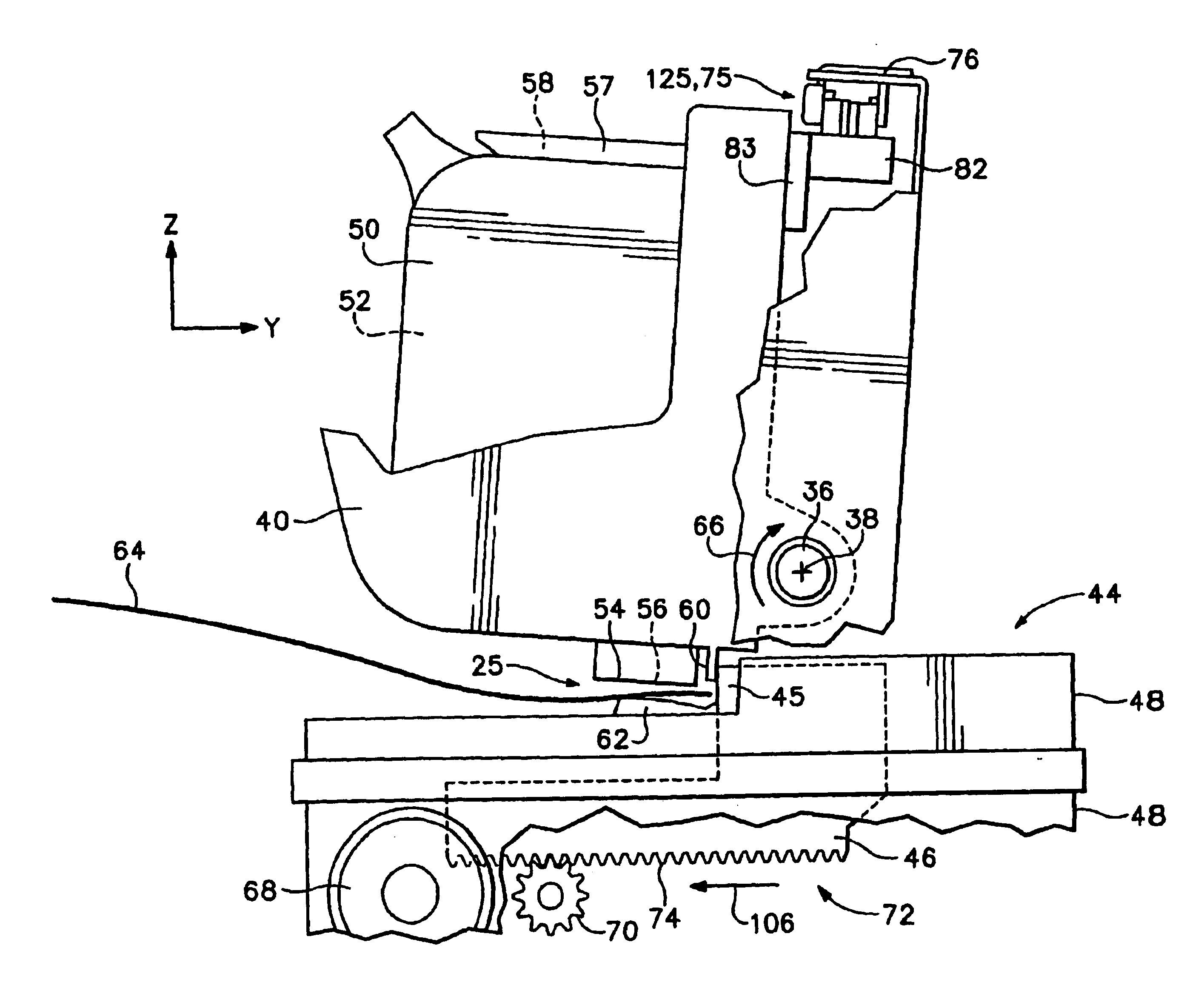
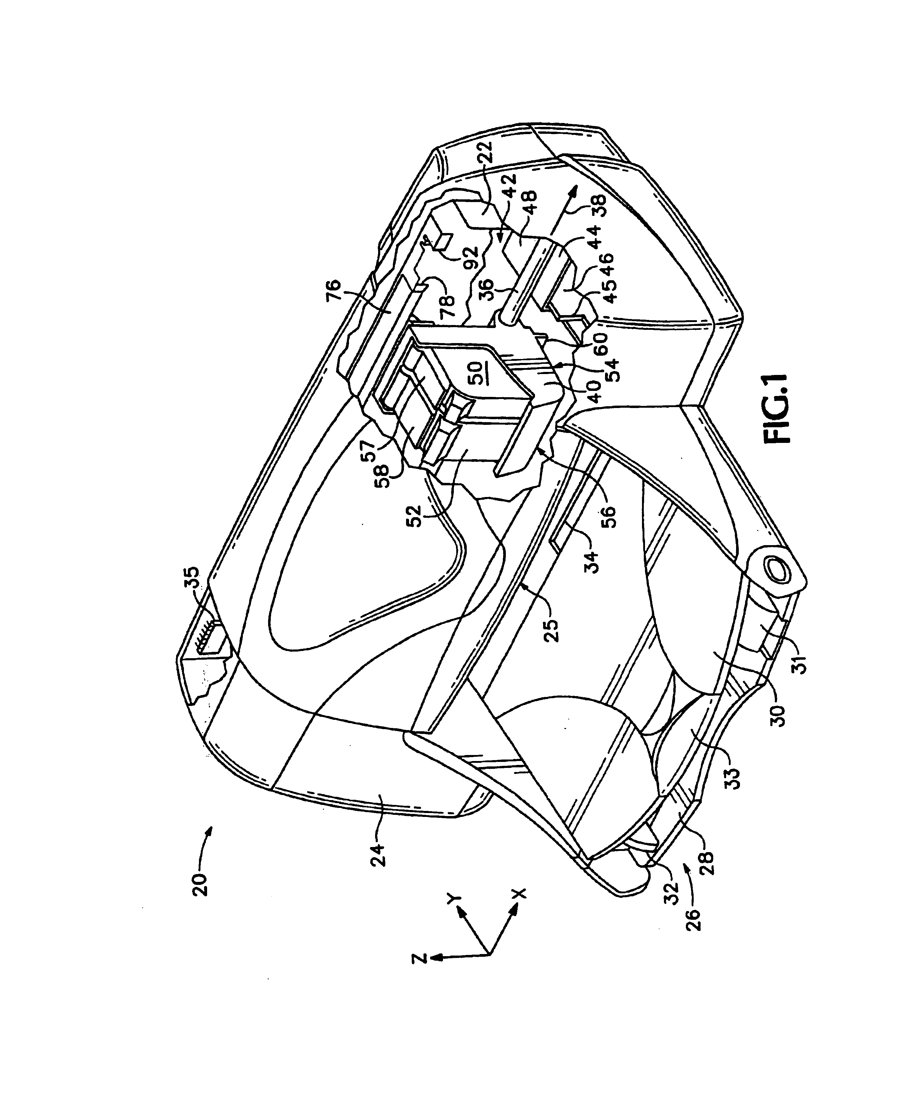
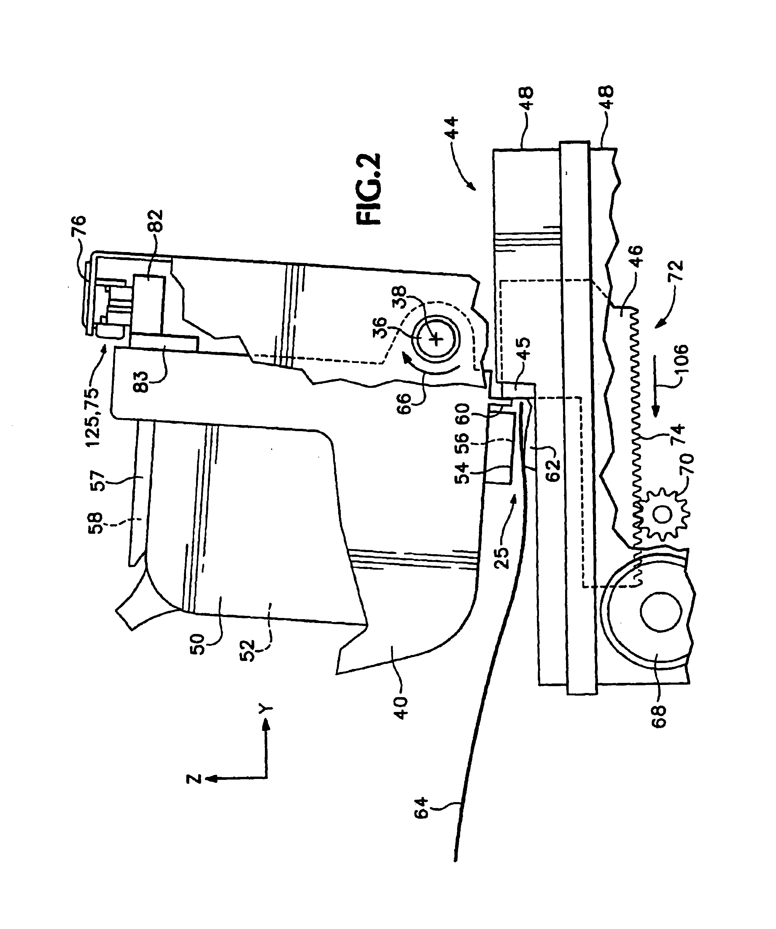
FIG. 1 illustrates an embodiment of a hardcopy mechanism, here shown as an inkjet printer 20, constructed in accordance with the present invention, which may be used for printing for business reports, correspondence, envelopes, desktop publishing, and the like, in an industrial, office, home or other environment. A variety of inkjet printing mechanisms are commercially available. For instance, some of the printing mechanisms that may embody the present invention include plotters, portable printing units, copiers, cameras, video printers, and facsimile machines, to name a few. For convenience the concepts introduced herein are illustrated in the environment of an inkjet printer 20.

While it is apparent that the printer components may vary from model to model, the typical inkjet printer 20 includes a chassis 22 surrounded by a housing or casing enclosure 24, typically of a plastic material. Sheets of print media are fed through a printzone 25 by an adaptive print handling system 26, co...


PUM


Abstract

An inkjet printer service station has a movable member that interacts with another printer subsystem, which is changeable between a first state and a second state. To vary the printhead-to-media spacing to accommodate different thickness of media, such as plain paper and envelopes, a cam-operated locking mechanism and a lever-operated mechanism raise and lower the inkjet printhead. Other printer subsystems may be transitioned between two or more states through motion of a service station movable member, including motion using gravity assist, centrifugal forces, or momentum to accomplish one of the transitions. Other locking mechanisms may be used to secure a subsystem in one state or another, such as electrical or electromechanical mechanisms, as well as other structurally equivalent forms beyond the specific preferred embodiments illustrated herein without departing from the broad concepts disclosed. An inkjet printing mechanism having such a system, along with methods of operation are also provided.

Description

The present invention relates generally to hardcopy mechanisms, and more particularly to a subsystem of a hardcopy mechanism which changes state in response to movement of a service station member, and in the illustrated hardcopy printing mechanism embodiment, to a subsystem which adjusts printhead-to-media spacing in a printzone to accommodate different media (e.g. paper) thicknesses in response to movement of the service station member to provide high quality images on varying thickness of media.Inkjet printing mechanisms use cartridges, often called “pens,” which shoot drops of liquid colorant, referred to generally herein as “ink,” onto a page. Each pen has a printhead formed with very small nozzles through which the ink drops are fired. To print an image, the printhead is propelled back and forth across the page, shooting drops of ink in a desired pattern as it moves. The particular ink ejection mechanism within the printhead may take on a variety of different forms known to th...

Claims


Application Information

Patent Timeline
Patent Type & Authority Patents(United States)
IPC IPC(8): B41J25/308
CPCB41J25/308B41J25/3082Y10T74/1494
Inventor FAIRCHILD, MICHAEL A.DONLEY, ALLAN D.
Owner HEWLETT PACKARD DEV CO LP
Why Eureka
Try Eureka