
Flush fitting LED turn signal

Inactive Publication Date: 2005-01-11
DESJARDINS GREGG P
View PDF15 Cites 16 Cited by
  • Summary
  • Abstract
  • Description
  • Claims
  • Application Information

AI Technical Summary

Benefits of technology

The flush fitting front LED turn signal has a flush mounted aluminum housing and an LED assembly with a domed lens extending beyond the upper surface of the housing. The housing, attached from behind the fairing, presents an outer surface flush with the front fairing of a motorcycle. Mounted within the housing is a multi-chip high-intensity, sunlight visible LED assembly, the dome of which protrudes beyond the surface of the housing and is visible from all angles. Mounted from within the fairing without any modification to the vehicle, the present invention presents a nearly seamless transition to the vehicle's bodywork, while providing the ruggedness and longevity of LED technology. The combination of housing and LED assembly may be provided in a variety of colors to match the factory finish.
It is another object of the invention to provide a turn signal for a motorcycle which is more rugged than the standard external mounted incandescent lamps supplied as original equipment on motorcycles through a flush mounted turn signal utilizing an LED assembly.
It is a further object of the invention to provide flush fitting front LED turn signals for a motorcycle in order to reduce the risk of damage if the motorcycle is laid on its side.
It is another object of the invention to provide a turn signal for motorcycles, which is visible from all viewing perspectives for safety purposes, and which is also mounted flush within the motorcycle fairing for producing an aesthetically pleasing, streamlined appearance.
It is an object of the invention to provide improved elements and arrangements thereof for the purposes described which is inexpensive, dependable and fully effective in accomplishing its intended purposes.

Problems solved by technology

While functional, these lights often take away from the overall streamlined appearance of the motorcycle.
The unique structural and environmental conditions experienced by motorcycles have resulted in a variety of lighting devices specifically developed for motorcycles, which have generally require additional support structures and do not maintain the streamline appearance of the motorcycle.
While motorcycle enthusiasts are sensitive to the issue of streamlined appearance, they are not willing to forgo practicality and safety, and therefore having a turn signal viewable from all positions is desired.

Method used


Image

  • Flush fitting LED turn signal
  • Flush fitting LED turn signal
  • Flush fitting LED turn signal

Examples


Embodiment Construction

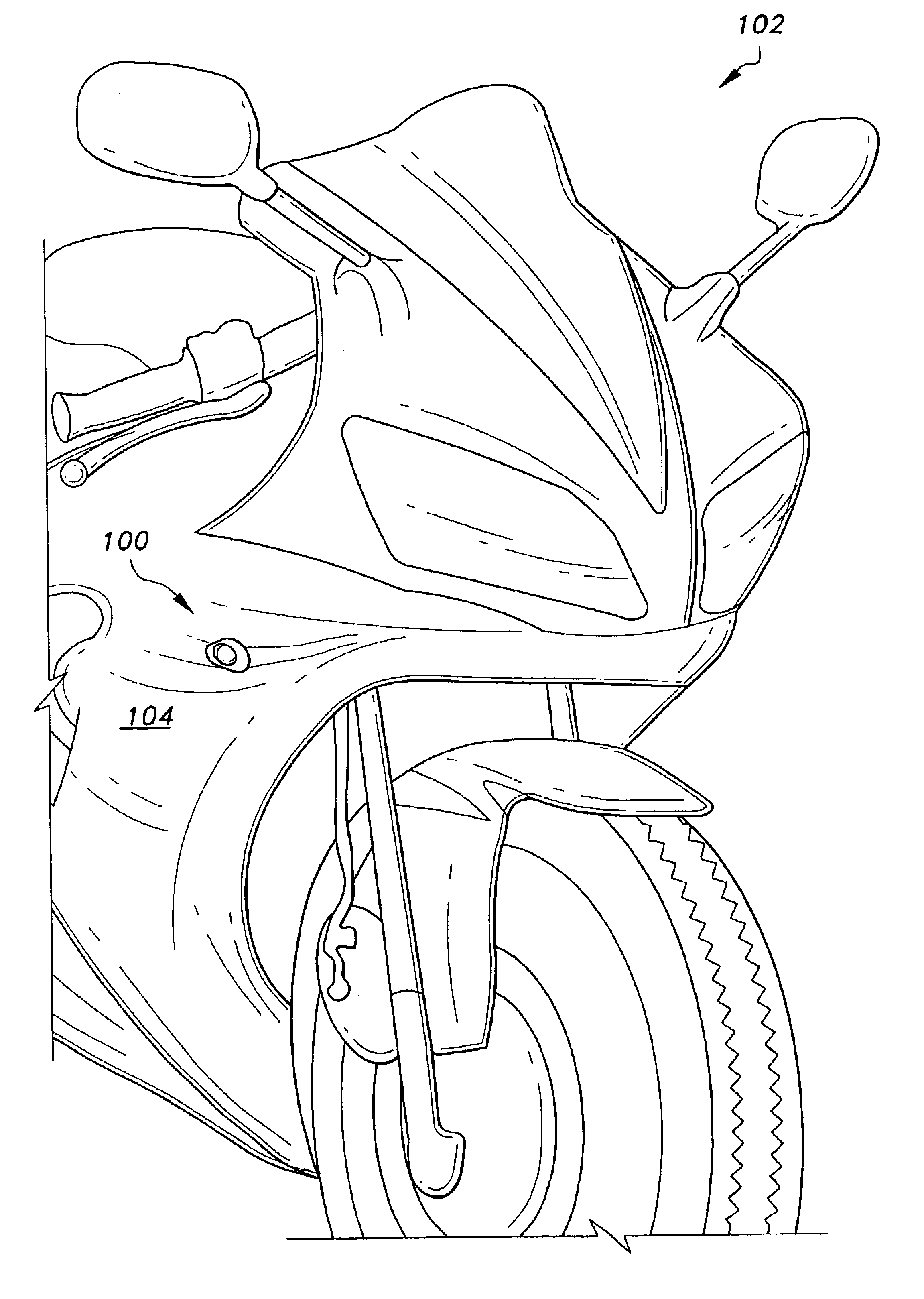
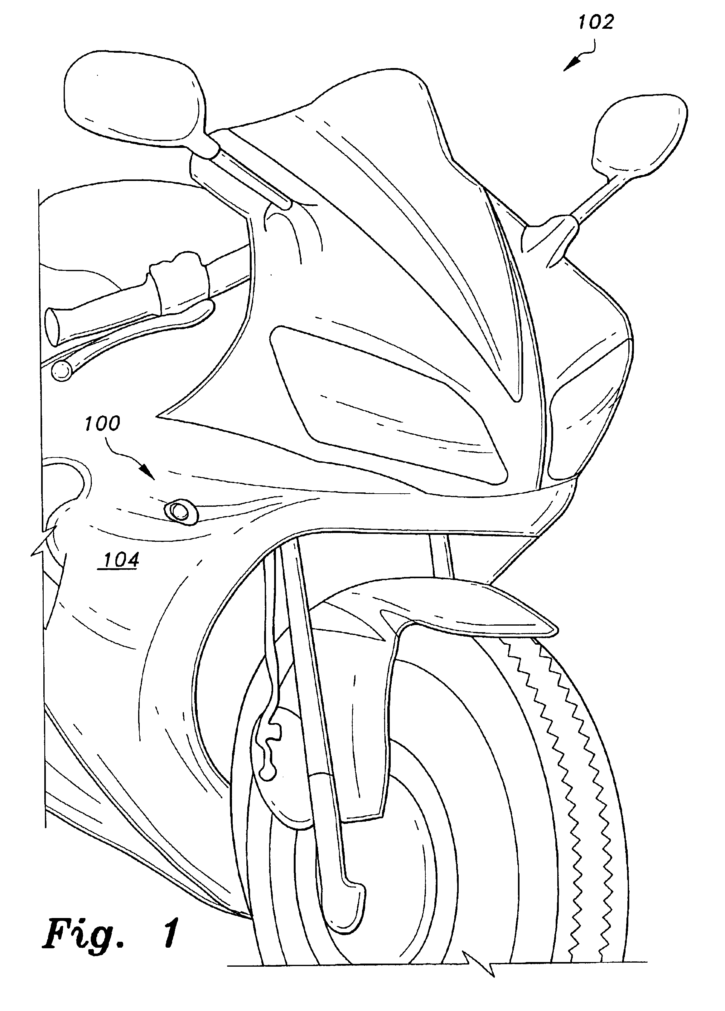
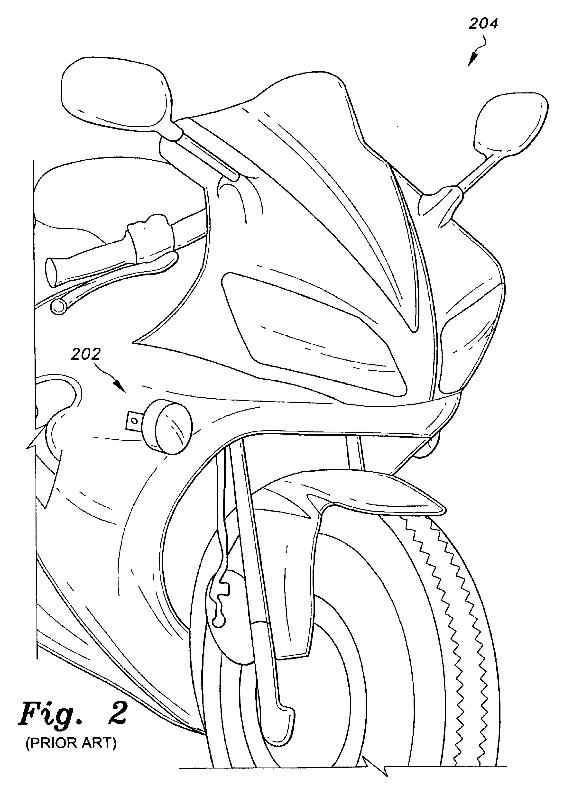
As shown in FIG. 1, the present invention is a flush fitting front turn signal 100 mounted within the front fairing 104 of a motorcycle 102 that replaces the original equipment, large protruding stock turn signals 202 that extend from the sides of a motorcycle 204 as shown in the prior art of FIG. 2. The flush fitting front turn signal 100 of the present invention presents a nearly seamless transition to a motorcycle fairing 104.

As shown in FIGS. 3 and 4, the flush fitting front turn signal 100 has a computer numeric controlled (CNC) machined aluminum housing 302 having a flat, planar, generally oval-shaped bottom surface 334 which is broader at one end than at the opposite end, and a preferably slightly convex top surface 308. The top surface 308 slopes downward, so that the lateral surface 310 is taller at the broad end of the housing 302 than at the narrow end of the housing 302. A first cylindrical bore 318 extends upward from the bottom surface 334 into the body of the housing ...


PUM


Abstract

The flush fitting front LED turn signal is adapted to provide a streamlined and nearly seamless transition to a motorcycle fairing. The present invention replaces bulky eternal front mounted motorcycle turn signals and utilizes the existing openings in the front fairing of the motorcycle. The present invention has an aluminum housing, and a LED assembly with a translucent dome extending outward from a bore within the housing.

Description

BACKGROUND OF THE INVENTION1. Field of the InventionThe present invention relates generally to light bulb assemblies for vehicles. More specifically, the invention is a flush fitting turn signal for motorcycles using light emitting diode (LED) lamps.2. Description of the Related ArtLight bulb assemblies for motorcycles or sportbikes typically are an assembly having an incandescent light bulb mounted in a reflector housing with a tinted lens or light-transmissive cover.Today's sportbikes purchased directly from the dealer are equipped with very large turn signals that protrude out from the sides of the front fairing. While functional, these lights often take away from the overall streamlined appearance of the motorcycle. Many owners remove these stock lights soon after purchasing the vehicle and have found alternative locations for more esthetically pleasing and functional front turn signals. One alternative has been handlebar-mounted lamps, utilizing either incandescent or light emi...

Claims


Application Information

Patent Timeline
IPC IPC(8): B62J6/00B60Q1/26
CPCB60Q1/2626B62J6/005B62J6/055
Inventor DESJARDINS, GREGG P.
Owner DESJARDINS GREGG P
Learn More