Flood control panel system

Inactive Publication Date: 2005-01-11
MARTINEZ ROSS R +1
View PDF13 Cites 57 Cited by
  • Summary
  • Abstract
  • Description
  • Claims
  • Application Information

AI Technical Summary

Benefits of technology

The use of the flood shield system safely controls flood waters resulting from natural disasters

Problems solved by technology

This is especially the case when dealing with floods where water can rise at alarming rates, engulfing entire towns and destroying family belongings that have been collected over many generations.
As a result, family heirlooms such as photographs, an

Method used


Image

  • Flood control panel system
  • Flood control panel system
  • Flood control panel system

Examples


Embodiment Construction

The best mode for carrying out the invention is presented in terms of its preferred embodiment, herein depicted within the FIGS. 1 through 4.

1. Detailed Description of the Figures

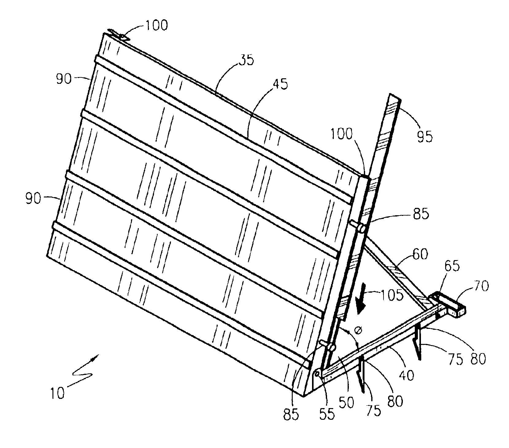
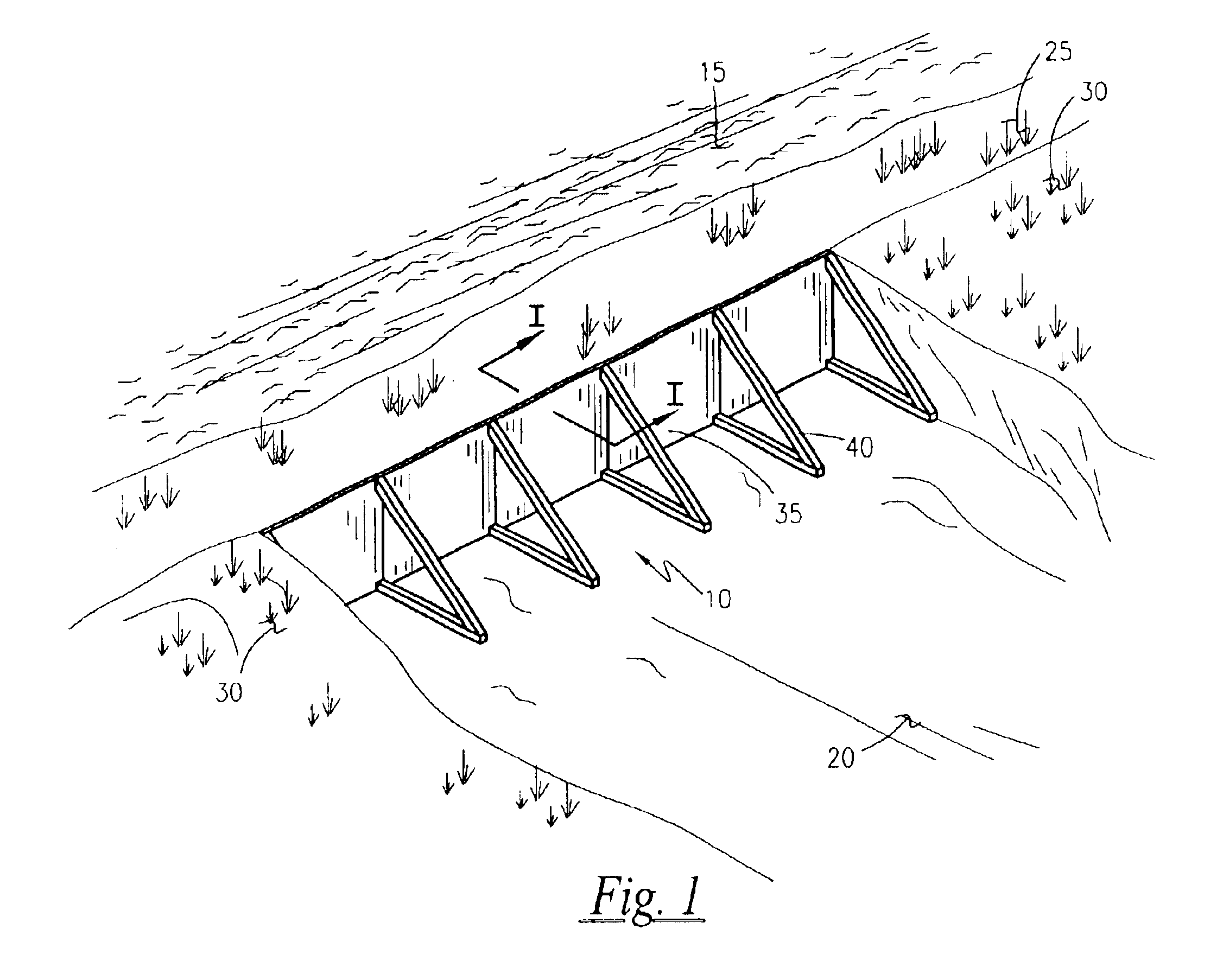
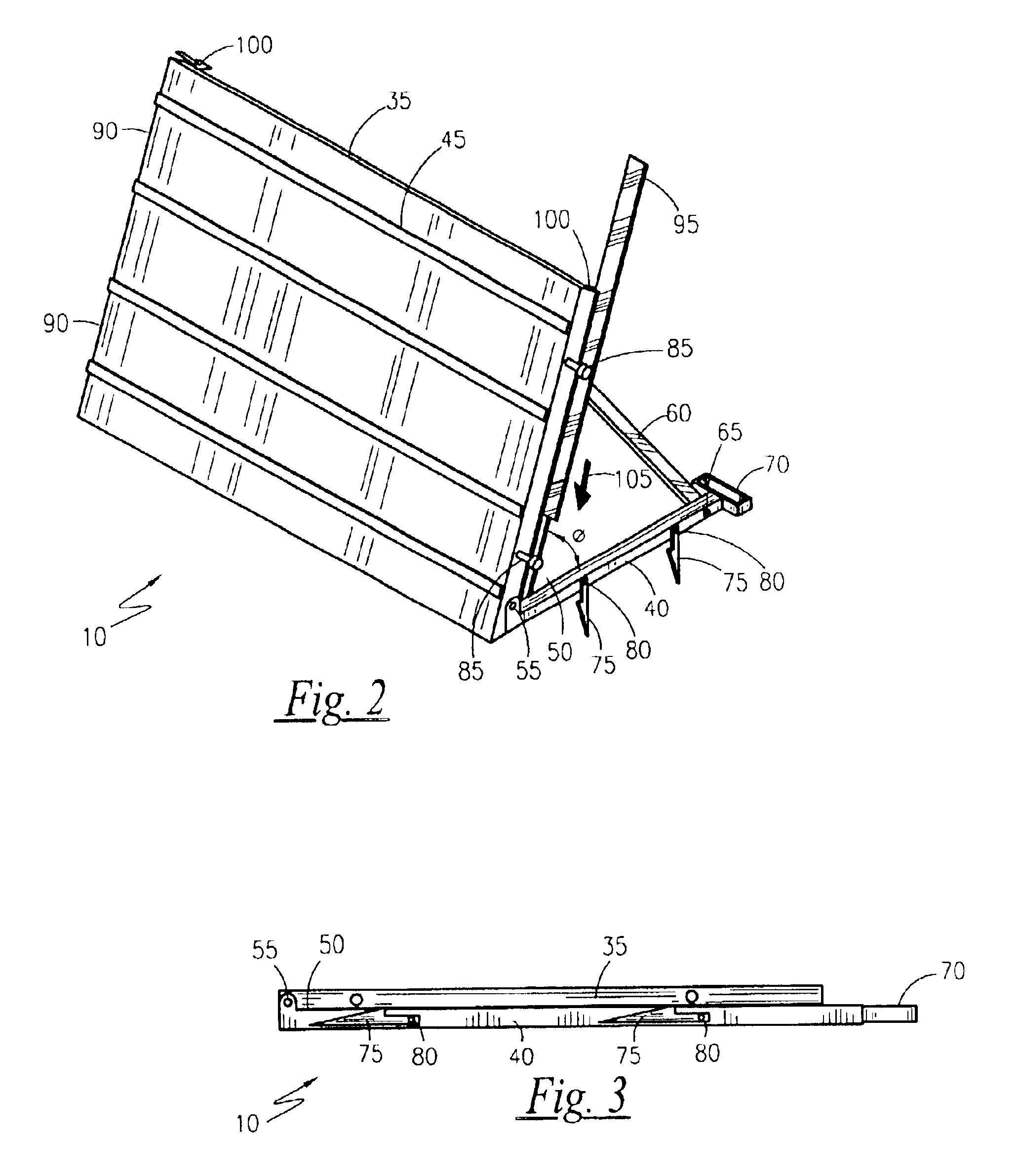
Referring first to FIG. 1, a pictorial representation of the flood control panel system 10, shown in an utilized state along a body of water, according to a preferred embodiment of the present invention is depicted. A flood control panel system 10 is shown erected in between a body of approaching flood waters 15 and an area of protected land 20. While the specific topography will vary from application to application, it is envisioned that the approaching flood waters 15 would be a lake, a river, a stream, a creek bed, a flood plain, or the like swollen from excessive rain or snow melt. Additionally, a barrier area 25, such as a beach or waterfront area, is present and is normally expected to be flooded. Areas of high ground 30 may or may not be present, but if present, provide an opportunity to terminate th...


PUM


Abstract

A modular flood control panel is provided having a base and supporting “A”-frame structure. The base locks into the ground, or supporting wall of sandbags, with a series of four adjustable angle stakes per each panel. The invention folds flat when not in use, for storage and for transportation on a truck to flood water areas. The panels are joined together with the use of a five inch wide joining slat that slides down into a channel on each side of each panel.

Description

RELATED APPLICATIONSThe present invention was first described in Disclosure Document Registration 509,499 filed on Apr. 8, 2002 under 35 U.S.C. §122 and 37 C.F.R. §1.14. There are no previously filed, nor currently any co-pending applications, anywhere in the world.BACKGROUND OF THE INVENTION1. Field of the InventionThe present invention relates generally to flood control systems and, more particularly, to a system of flood control panels that can be interlocked to form a barrier against flood waters.2. Description of the Related ArtAs is well known in the art, a When disaster strikes, every second counts in preventing the loss of life or property. This is especially the case when dealing with floods where water can rise at alarming rates, engulfing entire towns and destroying family belongings that have been collected over many generations. As a result, family heirlooms such as photographs, antiques and other irreplaceable items risk being lost forever, without hope for recovery. T...

Claims


Application Information

Patent Timeline
IPC IPC(8): E02B3/10
CPCE02B3/106Y02A10/30
Inventor MARTINEZ, ROSS R.MARTINEZ, RENATE H.
Owner MARTINEZ ROSS R
Why Eureka
Try Eureka