Horizontal fuel cell tube system and methods

a fuel cell and tube technology, applied in the field of horizontal fuel cell tube systems, can solve the problems of distributed generation of electricity and small scal

Inactive Publication Date: 2005-01-11
ACUMENTRICS
View PDF12 Cites 68 Cited by
  • Summary
  • Abstract
  • Description
  • Claims
  • Application Information

AI Technical Summary

Problems solved by technology

This increased consumption, together with the deregulation of electrical utilities in in...

Method used


Image

  • Horizontal fuel cell tube system and methods
  • Horizontal fuel cell tube system and methods
  • Horizontal fuel cell tube system and methods

Examples


Embodiment Construction

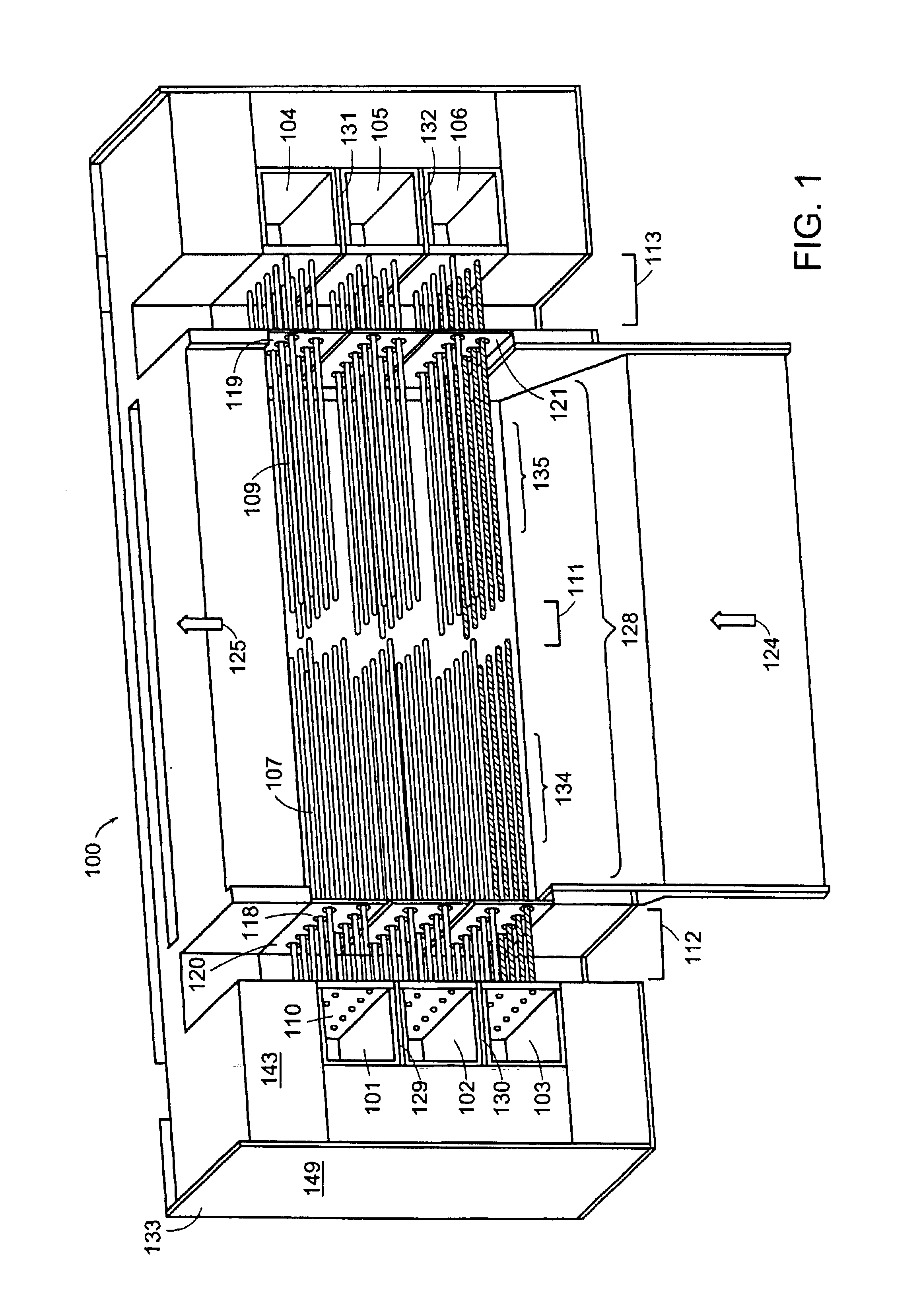
FIG. 1 shows a cross-sectional view of a dual injector tubular fuel cell system 100 according to an embodiment of the invention. In this embodiment, a hydrogen-containing fuel gas, such as natural gas, flows into two sets of fuel plenum chambers 101-103 and 104-106 located on opposite sides of system 100. After being pre-reformed in the fuel plenum chambers, the fuel gas flows out of each fuel plenum chamber 101-106 through a fuel gas injector 107, and toward the center of system 100. Each fuel gas injector 107 is a metal tube (such as a steel tube) affixed at its base (for instance, by welding) to a hole 110 in the wall of a fuel plenum chamber 101.

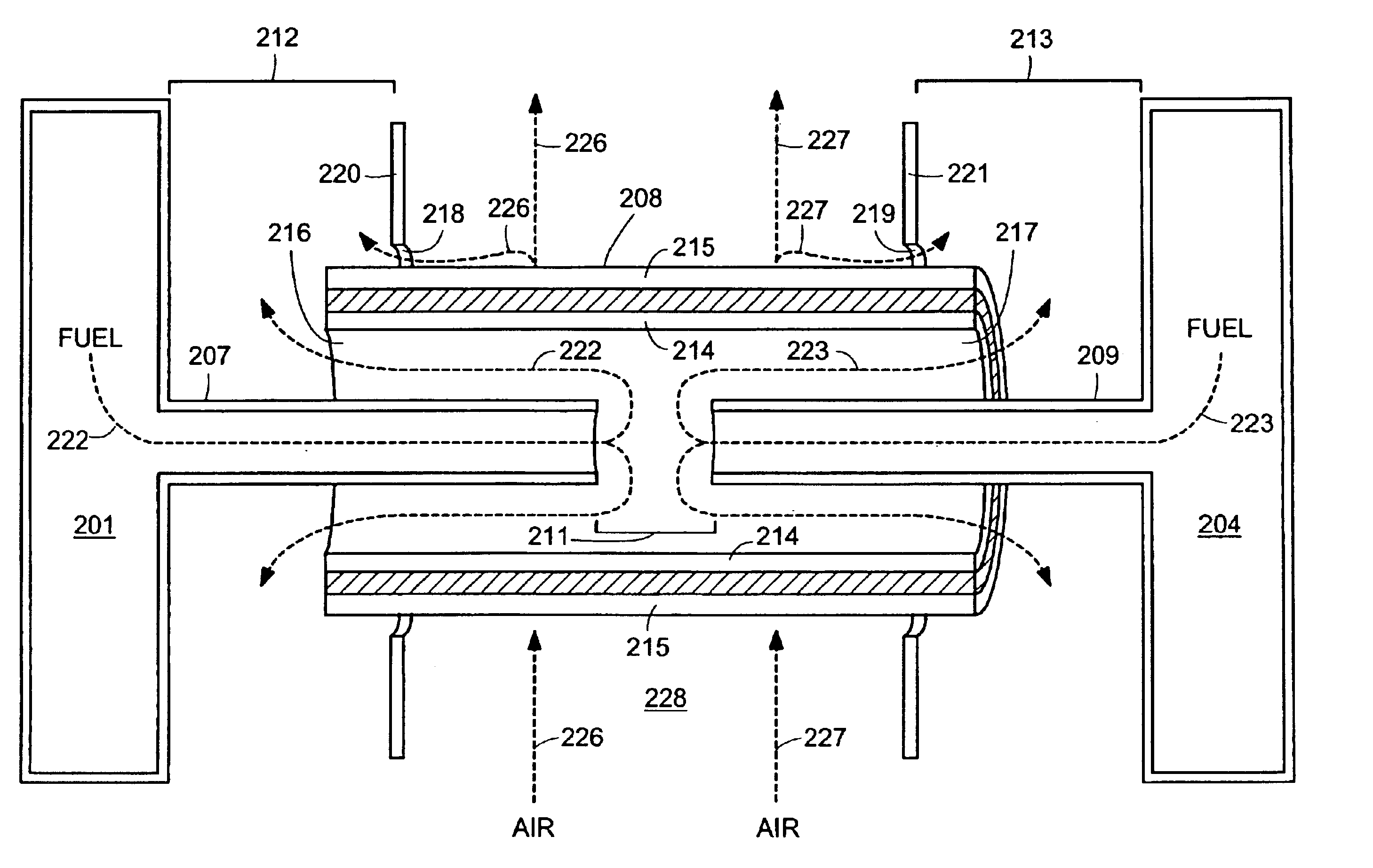
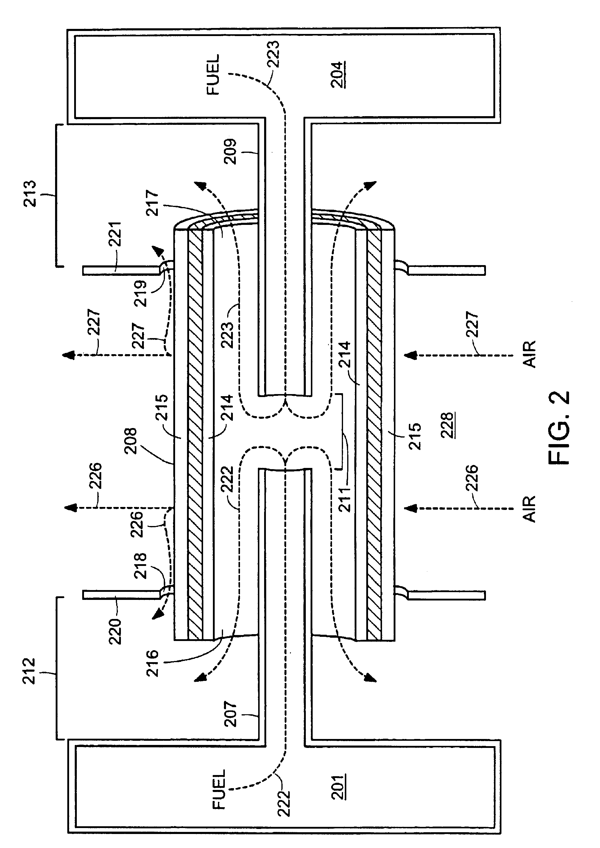
A tubular solid oxide fuel cell 208 (omitted from FIG. 1 for clarity) surrounds each opposing pair of fuel gas injectors 207, 209, as shown in the cross-sectional detail view of FIG. 2. Dashed lines 222 and 223 indicate the flow of fuel gas: first, in opposite directions away from a gap 211, that is between the ends of opposing fuel gas ...


PUM


Abstract

In one disclosed embodiment according to the invention, a fuel cell system for generating electrical power comprises: an open-ended tubular solid oxide fuel cell; a first fuel injector tube extending from a first fuel plenum chamber through one open end of the fuel cell; and a second fuel injector tube extending from a second fuel plenum chamber through another open end of the fuel cell; wherein the first and second fuel injector tubes form a gap within the fuel cell from which a hydrogen-containing fuel gas may flow towards the open ends of the fuel cell. Further related systems and method are also disclosed.

Description

TECHNICAL FIELDThe invention relates to fuel cell systems and associated methods, and in particular to fuel cell stack designs for tubular solid oxide fuel cells.BACKGROUND ARTWorldwide forecasts show electricity consumption increasing dramatically in the next decades, largely due to economic growth in developing countries that lack national power grids. This increased consumption, together with the deregulation of electrical utilities in industrialized nations, creates the need for small scale, distributed generation of electricity.Fuel cells are a promising technology for providing distributed generation of electricity. A fuel cell places an oxidizing gas, such as air, and a hydrogen-containing fuel, such as hydrogen or natural gas, on opposite sides of an electrolyte in such a way that they combine to form water and electricity. Such a reaction requires a cathode and an anode composed of porous materials, and an ionically-conducting electrolyte. In solid oxide fuel cells, the ele...

Claims


Application Information

Patent Timeline
IPC IPC(8): H01M8/24H01M8/06H01M8/04H01M8/12H01M8/02
CPCH01M8/0612H01M8/2415H01M8/243H01M8/2475H01M8/0202Y02E60/525H01M8/04007H01M8/04022H01M8/04067H01M8/0625H01M8/1206H01M8/249H01M2008/1293H01M2300/0074Y02E60/50H01M8/0256H01M8/1231H01M8/2484H01M8/02H01M8/24H01M8/2485
Inventor BROWN, MICHAELFENTON, BASILGAW, KEVINFERNANDES, NEILMOOK, GARY A.SMITH, HUGH L.TOMPSETT, GEOFFREYFINNERTY, CAINELITKA, ANTHONY F.BOUVIER, VIRGINIENEGROTTI, KEVIN H.
Owner ACUMENTRICS
Why Eureka
Try Eureka