Planarity diagnostic system, E.G., for microelectronic component test systems

a diagnostic system and microelectronic component technology, applied in the direction of electrical testing, measurement devices, instruments, etc., can solve the problems of increasing difficulty in ensuring proper contact between the probe of the test card and the terminal of the microelectronic component, and the high degree of quality and cost consideration of most microelectronics manufacturers

Inactive Publication Date: 2005-01-11
MICRON TECH INC
View PDF108 Cites 27 Cited by
  • Summary
  • Abstract
  • Description
  • Claims
  • Application Information

AI Technical Summary

Problems solved by technology

The microelectronics industry is highly competitive and most microelectronics manufacturers are highly sensitive to quality and cost considerations.
As microelectronic components and the terminals carried by those components are made progressively smaller, it becomes increasingly difficult to insure proper contact between the probes of the test card and the terminals of the microelectronic component.
Sometimes when these elements are not precisely aligned, one or more of the probes will not establish adequate contact with the intended terminal on the microelectronic component.
When this data is analyzed, the test system may improperly indicate that an acceptable microelectronic component is defective.
Such false rejections can be expensive and time consuming.
If this probe tip plane and a plane of the microelectronic component terminals are not parallel to one another, probe tips intended to contact terminals on one side of the array may be overly compressed or stressed, while terminals on the other side of the terminal array do not adequately contact the intended probes.
Unfortunately, this can place undue stress on the microelectronic component being tested and on the test card.

Method used


Image

  • Planarity diagnostic system, E.G., for microelectronic component test systems
  • Planarity diagnostic system, E.G., for microelectronic component test systems
  • Planarity diagnostic system, E.G., for microelectronic component test systems

Examples


Embodiment Construction

A. Overview

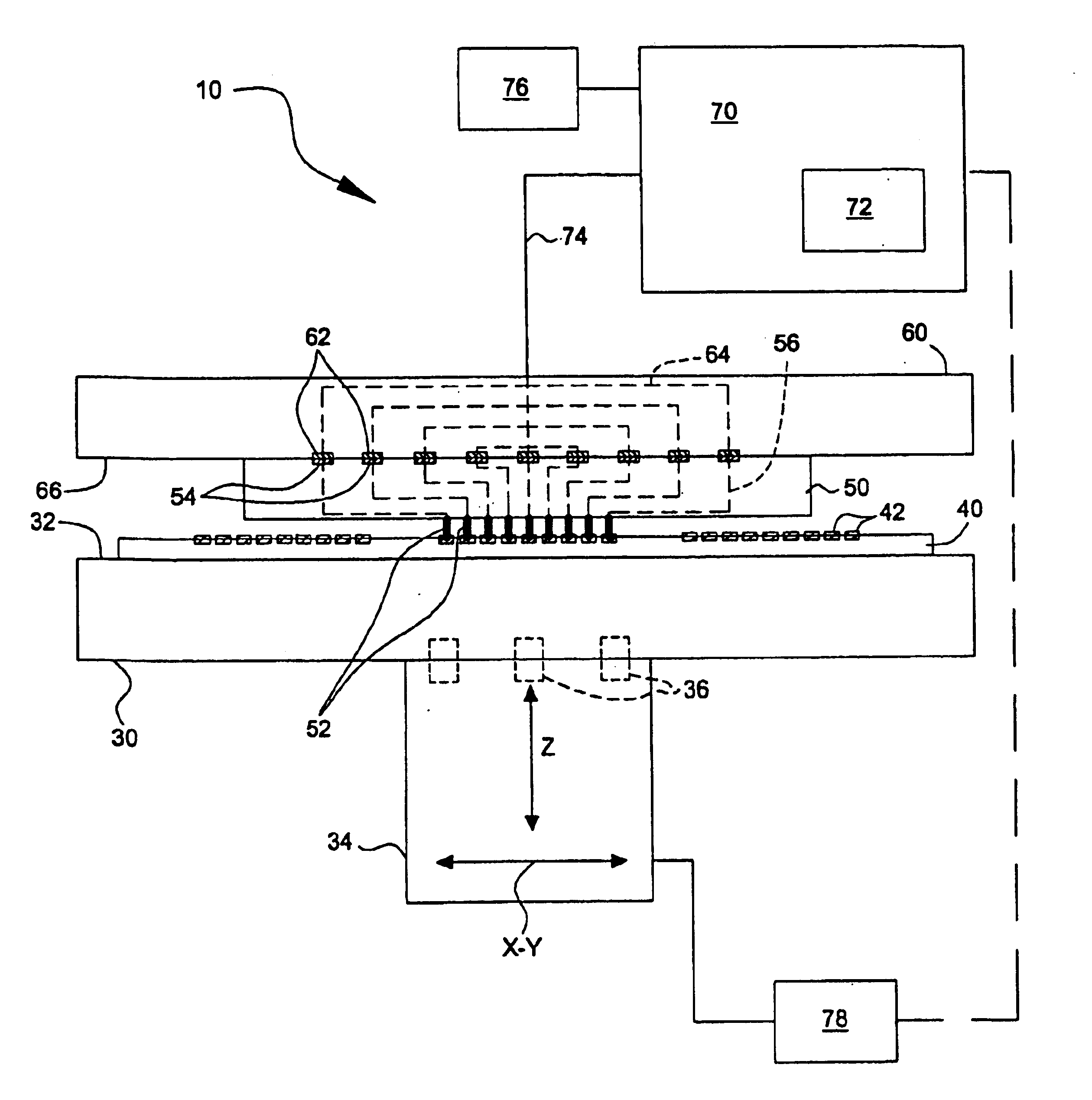
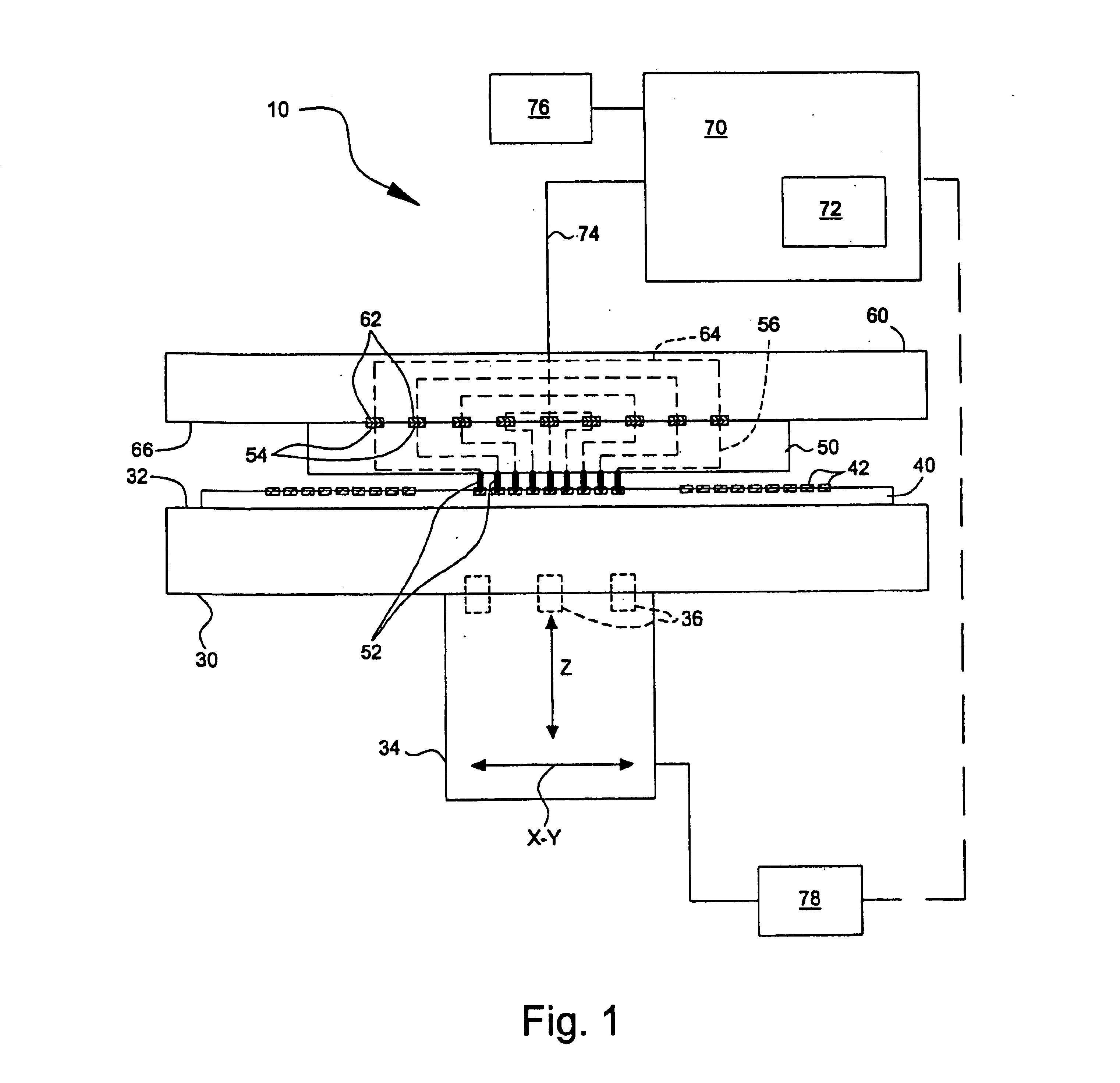
Various embodiments of the present invention provide microelectronic component test systems and methods for verifying planarity of a head which holds a test card with respect to a microelectronic component support. The term “microelectronic component” may encompass a variety of articles of manufacture, including memory modules (e.g., SIMM, DRAM, or flash memory) ASICs, processors, semiconductor wafers, semiconductor dyes singulated from such wafers, assemblies of other microelectronic components, or any of a variety of other types of microelectronic devices or components therefor. The term “probe card” or “test card” may encompass a variety of architectures, including both rigid structures and flexible structures.

In one embodiment, the present invention provides a method of using a microelectronic component test system of the type which contacts a microelectronic component carried by a microelectronic component support with a plurality of test probes on a test card carrie...


PUM


Abstract

Maintaining proper planarity of elements of a microelectronic component test system helps ensure reliable operation of the test system. This disclosure suggests test systems and methods for verifying planarity of, for example, a head and a support surface of a microelectronic component test system. In one exemplary method, a probe card is mounted to and electrically coupled to a head of a microelectronic component test system. The probe card has an array of probes. A contact surface of the support is moved with respect to the head and a change in contact condition of each of the probes is recorded in a first data set. The orientation of the probe card with respect to the contact surface is changed, the contact surface is moved with respect to the head again, and a change in contact condition of each of the probes is recorded in a second data set.

Description

BACKGROUNDThe present invention provides certain improvements in microelectronic component testing. More particularly, certain embodiments of the invention provide methods and systems for verifying planarity of elements of a microelectronic component test system, e.g., a semiconductor wafer prober.The microelectronics industry is highly competitive and most microelectronics manufacturers are highly sensitive to quality and cost considerations. Most microelectronics manufacturers require that suppliers of microelectronic components test the performance of each microelectronic component before shipment to minimize the manufacturer's product losses. Microelectronics are commonly tested by establishing temporary electrical connections between a test system and electrical terminals on the microelectronic component.Temporary electrical connection between the test system and the terminals of the microelectronic component is conventionally established using a test card carrying a plurality ...

Claims


Application Information

Patent Timeline
Patent Type & Authority Patents(United States)
IPC IPC(8): G01R1/073
CPCG01R1/07314G01R31/2893G01R1/07378
Inventor MARTIN, MICHAEL H.CRUMP, BRETT
Owner MICRON TECH INC
Why Eureka
Try Eureka