

Write driver for a magnetoresistive memory
a write driver and magnetoresistive technology, applied in the direction of information storage, static storage, digital storage, etc., can solve the problem of difficult production of such mrams
- Summary
- Abstract
- Description
- Claims
- Application Information
AI Technical Summary
Problems solved by technology
Method used
Image

Examples
Embodiment Construction
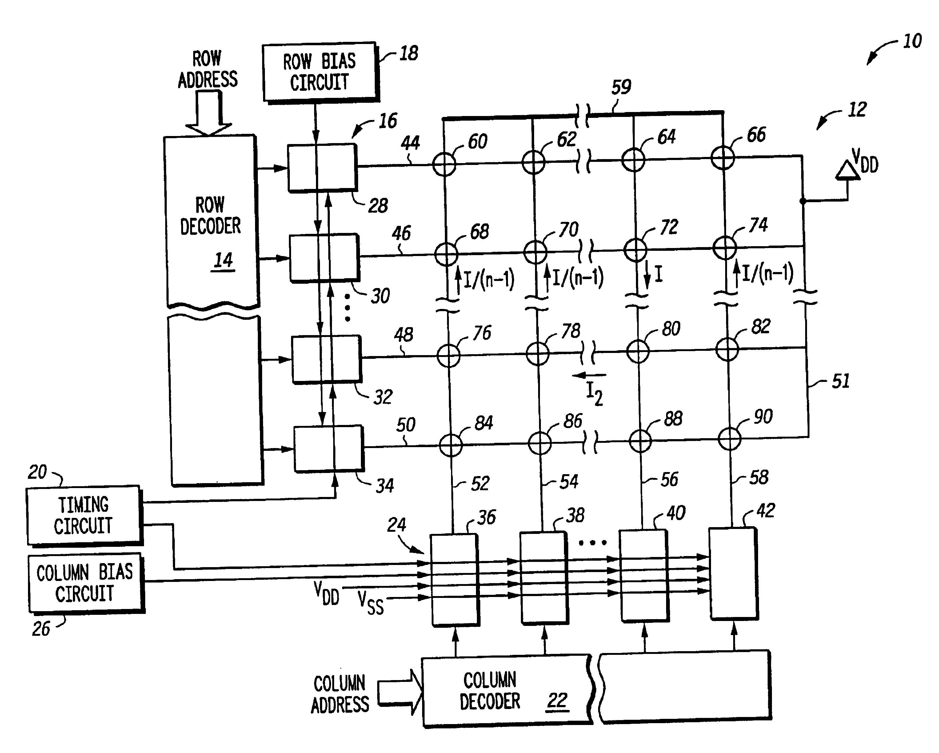
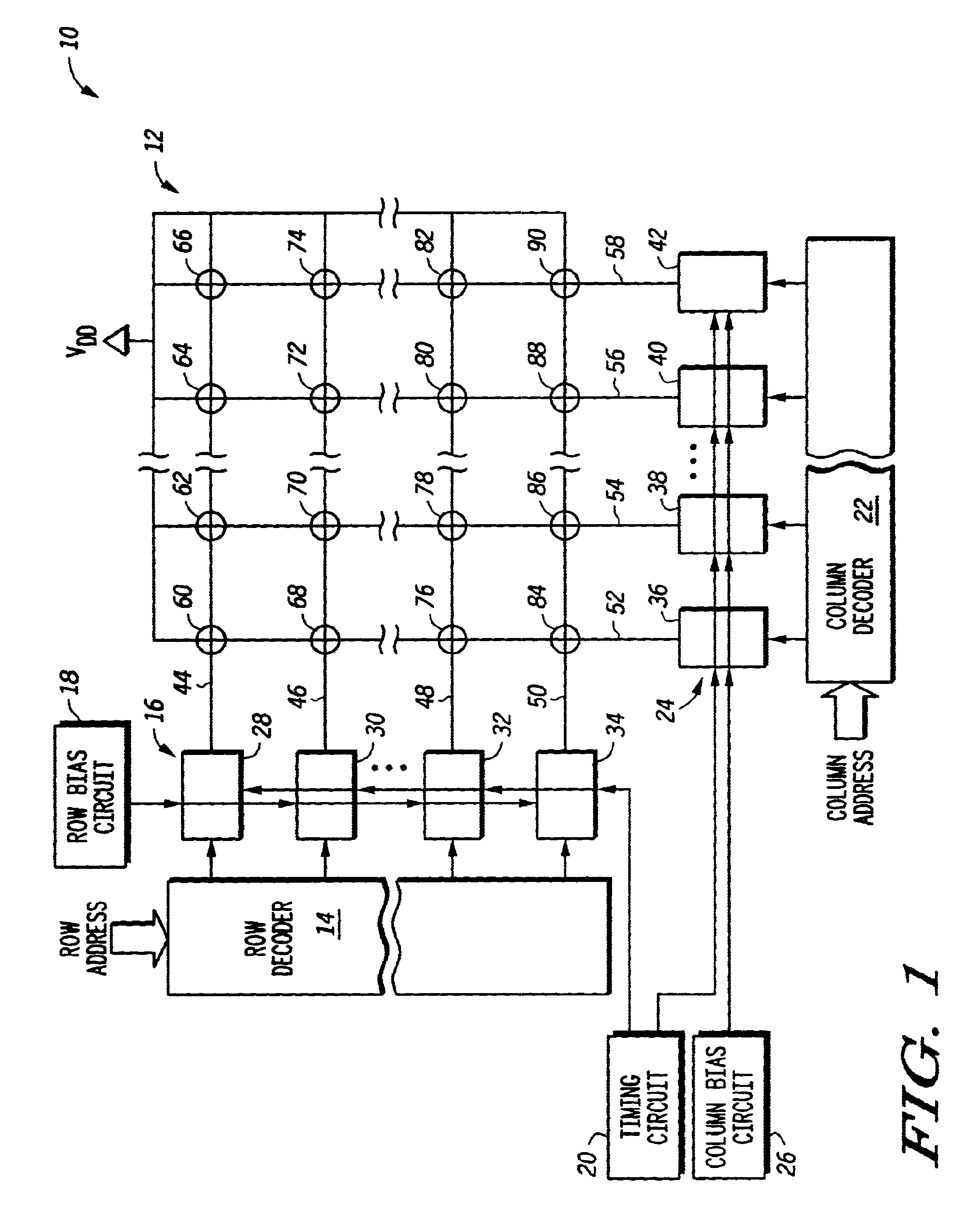
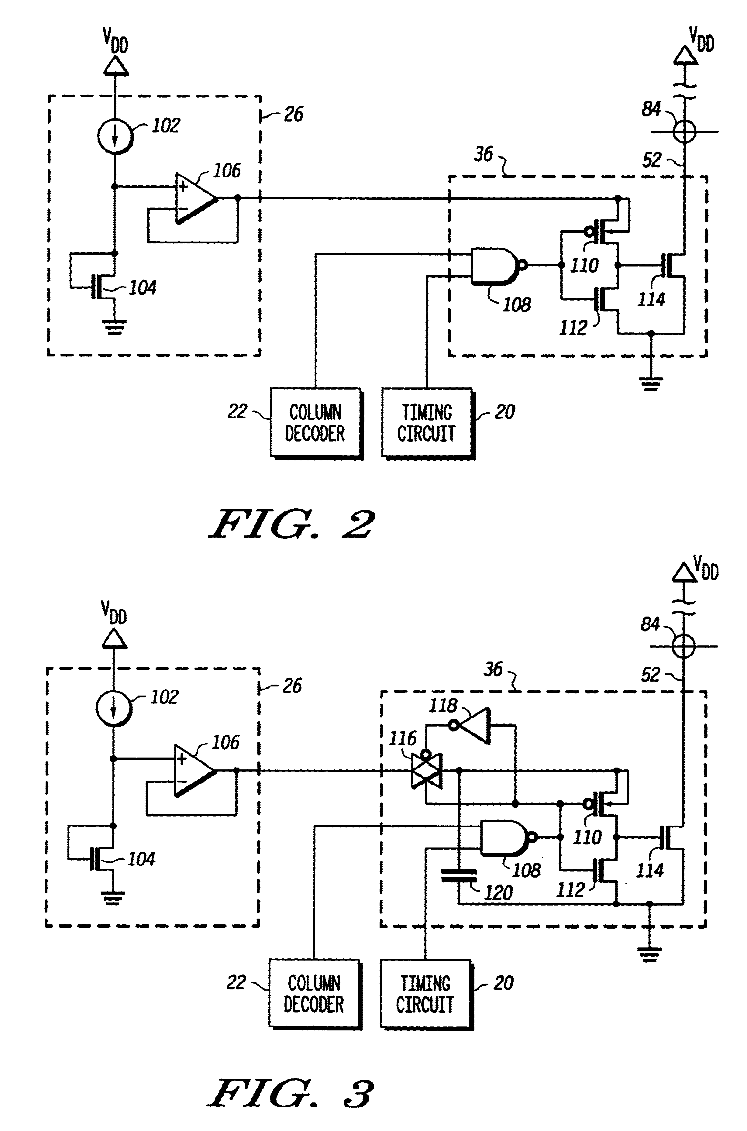
A write driver uses a reference current that is reflected to a driver circuit by a voltage. The driver circuit is sized in relation to the device that provides the voltage so that the current through the driver is a predetermined multiple of the reference current. This voltage is coupled to the driver circuit through a switch. The switch is controlled so that the driver circuit only receives the voltage when the write line is to have write current through it as determined by a decoder responsive to an address. The driver is affirmatively disabled when the write line is intended to not have current passing through it. As an enhancement to overcome ground bounce due to high currents, the input to the driver can be capacitively coupled to the ground terminal that experiences such bounce. Additional enhancements provide benefits in control of the current amplitude and edge rate. This is better understood with reference to the drawings and the following description.
Shown in FIG. 1 is a m...
PUM
 Abstract
Description
Claims
Application Information