Cone beam computed tomography with a flat panel imager

a computed tomography and flat panel imager technology, applied in the field of cone beam computed tomography system, can solve the problems of limited delivery of increased dose, increased volume of normal tissue, intrafraction errors, etc., and achieve the effect of reducing radiation treatment errors, improving radiation therapy precision, and adequate visualization

Inactive Publication Date: 2005-01-11
WILLIAM BEAUMONT HOSPITAL
View PDF21 Cites 406 Cited by
  • Summary
  • Abstract
  • Description
  • Claims
  • Application Information

AI Technical Summary

Benefits of technology

[0021]Each aspect of the present invention provides the advantage of generating KV projection images in a cone beam computerized tomography system that provide adequate visualization of soft-tissue structures so as to reduce errors in radiation treatment resulting from organ motion.
[0022]Each aspect of the present invention provides an apparatus and method for improving the precision of radiation therapy by incorporating a cone beam computerized tomography imaging system in the treatment room, the 3-D images from which are used to modify current and subsequent treatment plans.
[0023]Each aspect of the present invention represents a significant shift in the practice of radiation therapy. Not only does the high-precision, image-guided system for radiation therapy address the immediate need to improve the probability of cure through dose escalation, but it also provides opportunity for broad innovation in clinical practice.
[0024]Each aspect of the present invention may permit alternative fractionation schemes, permitting shorter courses of therapy and allowing improved integration in adjuvant therapy models.

Problems solved by technology

Unfortunately, delivery of increased dose is limited by the presence of adjacent normal structures and the precision of beam delivery.
Furthermore, the location and orientation of the lesion can vary during a single treatment session (resulting in intrafraction errors) due to normal biological processes, such as breathing, peristalsis, etc.
Applying large margins necessarily increases the volume of normal tissue that is irradiated, thereby limiting the maximum dose that can be delivered to the lesion without resulting in complication in normal structures.
However, it is often the case that the maximum dose that can be safely delivered to the target volume is limited by the associated dose to surrounding normal structures incurred through the use of margins.
This obvious shortcoming can be alleviated by implanting radio-opaque markers on the lesion; however, this technique is invasive and is not applicable to all treatment sites.
The former approach is a fairly expensive solution, requiring the installation of a dedicated computerized tomography scanner in the treatment room.
Typically, such images suffer from poor contrast resolution and provide, at most, visualization of bony landmarks relative to the field edges.
There are constraints associated with image reconstruction under a cone-beam geometry.
The poor optical coupling efficiency (−10−4) between the phosphor and the CCD significantly reduces the detective quantum efficiency (DQE) of the system.
However, such a system 200 still would not likely provide adequate visualization of soft-tissue structures and hence be limited in the degree to which it could reduce errors resulting from organ motion.

Method used


Image

  • Cone beam computed tomography with a flat panel imager
  • Cone beam computed tomography with a flat panel imager
  • Cone beam computed tomography with a flat panel imager

Examples


second embodiment

f FIG. 17 when employing a support for a flat-panel imager according to the present invention;

[0048]FIGS. 21(a)-(b) schematically shows a front view of the wall-mounted cone beam computerized tomography system of FIG. 17 when employing a third embodiment of a support for a flat-panel imager according to the present invention;

[0049]FIG. 22 is a diagrammatic view of a portable cone beam computerized tomography system employing a flat-panel imager according to fifth embodiment of the present invention;

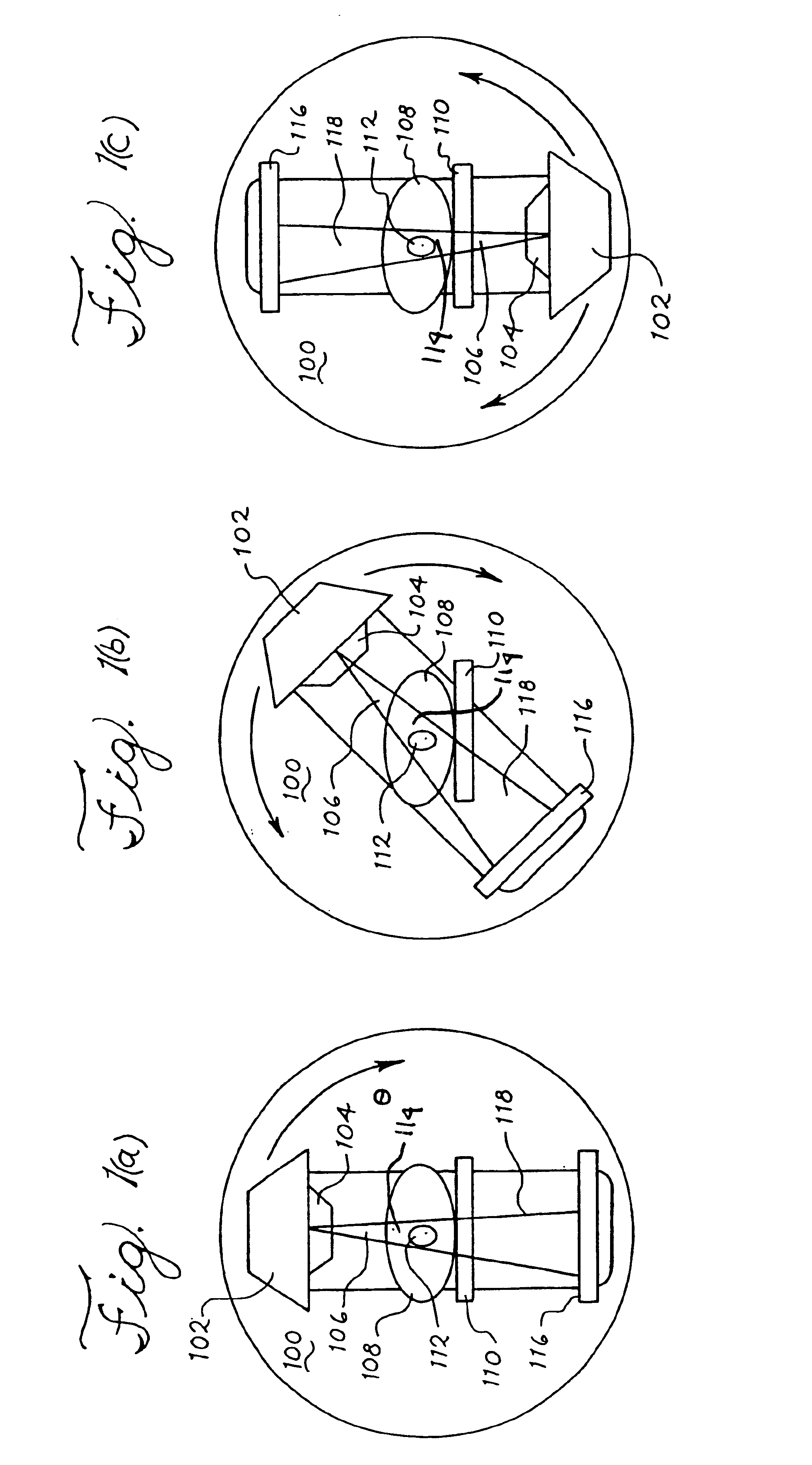
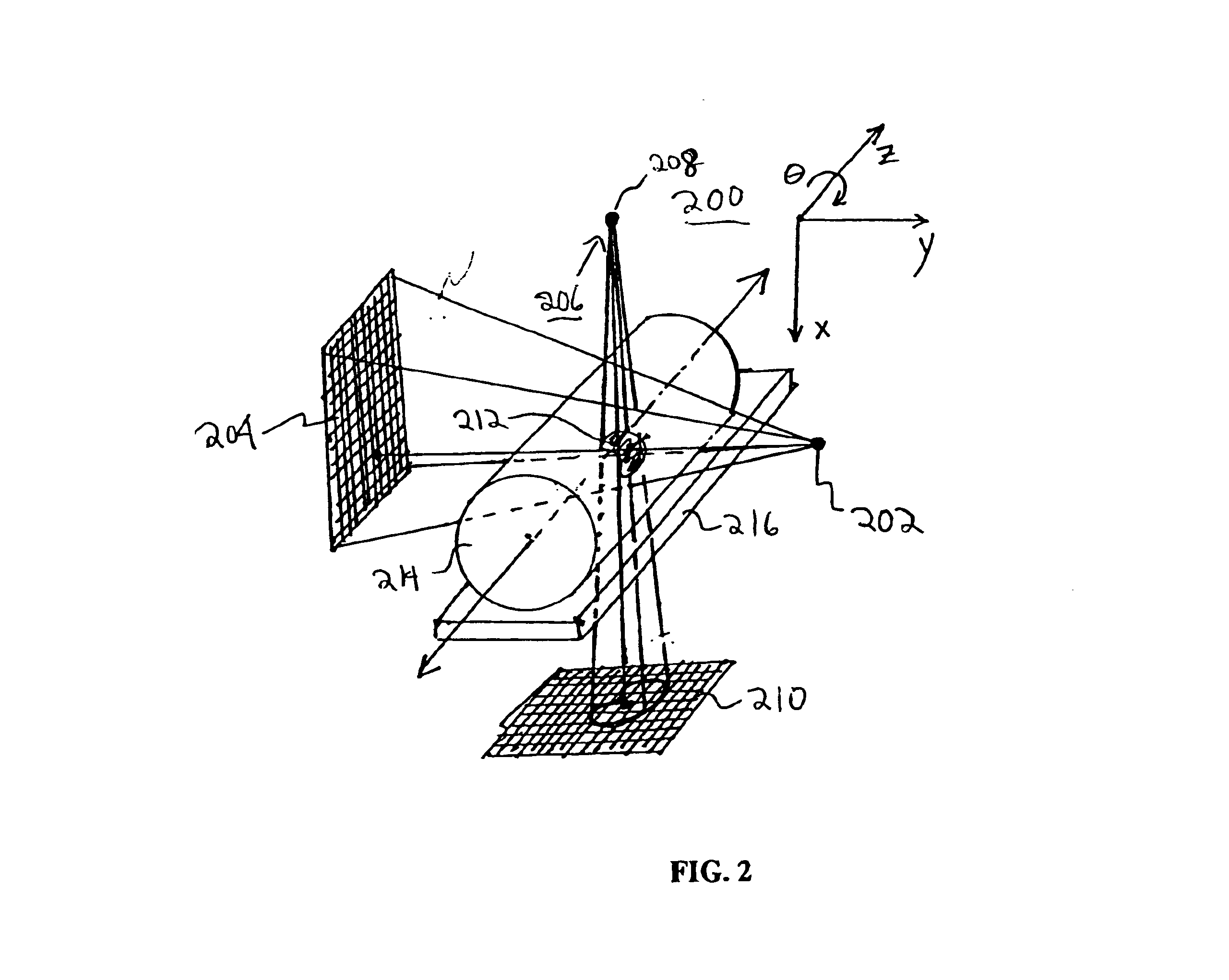
[0050]FIGS. 23(a)-(d) are diagrammatic sketches illustrating the geometry and operation of the cone beam computerized tomography imaging systems of FIGS. 17-22;

[0051]FIG. 24 is a flow-chart showing an embodiment of the processes involved in acquiring a cone beam computerized image for the cone beam computerized tomography imaging systems of FIGS. 17-22;

[0052]FIG. 25 is a perspective drawing illustrating an embodiment of a method for geometric calibration of the imaging and treatment deliv...


PUM


Abstract

A radiation therapy system that includes a radiation source that moves about a path and directs a beam of radiation towards an object and a cone-beam computer tomography system. The cone-beam computer tomography system includes an x-ray source that emits an x-ray beam in a cone-beam form towards an object to be imaged and an amorphous silicon flat-panel imager receiving x-rays after they pass through the object, the imager providing an image of the object. A computer is connected to the radiation source and the cone beam computerized tomography system, wherein the computer receives the image of the object and based on the image sends a signal to the radiation source that controls the path of the radiation source.

Description

[0002]Applicants claim, under 35 U.S.C. § 119(e), the benefit of priority of the filing date of Feb. 18, 2000, of U.S. Provisional Patent Application Ser. No. 60 / 183,590, filed on the aforementioned date, the entire contents of which are incorporated herein by reference.BACKGROUND OF THE INVENTION[0003]1. Field of the Invention[0004]The present invention relates generally to a cone-beam computed tomography system and, more particularly, to a cone-beam computed tomography system that employs an amorphous silicon flat-panel imager for use in radiotherapy applications where the images of the patient are acquired with the patient in the treatment position on the treatment table.[0005]2. Discussion of the Related Art[0006]Radiotherapy involves delivering a prescribed tumorcidal radiation dose to a specific geometrically defined target or target volume. Typically, this treatment is delivered to a patient in one or more therapy sessions (termed fractions). It is not uncommon for a treatmen...

Claims


Application Information

Patent Timeline
Patent Type & Authority Patents(United States)
IPC IPC(8): A61B6/03A61B6/00A61N5/10G21K5/00A61B6/06G01T1/20G01T1/24G21K5/02
CPCA61B6/032A61B6/4085A61B6/466A61B6/583A61N5/1049A61B6/508A61B6/4458A61B6/4405A61B6/482A61N5/1038A61N5/1065A61N5/1069A61N2005/1061A61B6/027A61B6/06
Inventor JAFFRAY, DAVID A.WONG, JOHN W.SIEWERDESEN, JEFFREY H.
Owner WILLIAM BEAUMONT HOSPITAL
Why Eureka
Try Eureka