
Methods and apparatus for decision making of system of mobile robotic vehicles

Inactive Publication Date: 2005-01-11
SOLOMON RES
View PDF2 Cites 127 Cited by
  • Summary
  • Abstract
  • Description
  • Claims
  • Application Information

AI Technical Summary

Benefits of technology

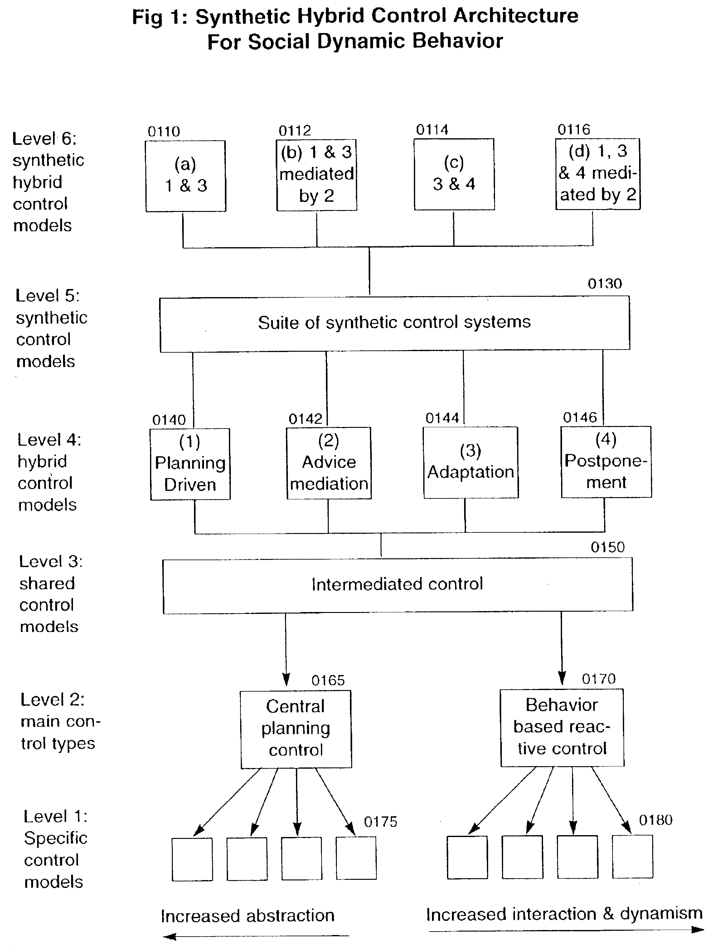
In one embodiment of the present system, both the swarm level and the squad level involve hierarchical control in which a centralized leader controls the drone followers. This approach benefits from clear lines of authority and mission focus. This approach also sustains the moral responsibility necessary for combat interaction by carefully structuring the program parameters to strike specific kinds of targets.
Collective behaviors of automated mobile robots are most fully expressed in aggregation and reaggregation processes that are well implemented in the present invention. Combat applications of aggregation present an optimal venue for the geometric grouping and regrouping of automated mobile agents as they interact with the changing environment. This complex self-organizing system more optimally models battlefield activity so that it emulates, and transcends, biological models that have evolved over millions of years.

Problems solved by technology

The U.S. Military has several fundamental strategic problems.
Finally, the problem exists of how to organize and coordinate automated weapons to work in a coherent integrated systems structure.
Earlier weapons are relatively primitive and stand-alone.
Now in the early stages of development and use, these unmanned vehicles are not generally used in groups that can work together for optimized collective effectiveness.
The main problem, however, is that central systems cannot plan well in an uncertain or unpredictable environment in which there is change.
This approach to robotic control, however, lacks the planning needed for optimal coordination between groups of robots for a common objective.
Third, the “adaptation” model continuously alters reaction by focusing on changing conditions.
Developing methods to organize collectives of automated robotic vehicles is one of the most challenging and complex problems in computer science, artificial intelligence and robotics research.
These challenges involve the need to develop original technological approaches in computation, communications, networking, materials, energy supply and artificial intelligence.

Method used


Image

  • Methods and apparatus for decision making of system of mobile robotic vehicles
  • Methods and apparatus for decision making of system of mobile robotic vehicles
  • Methods and apparatus for decision making of system of mobile robotic vehicles

Examples


Embodiment Construction

The present disclosures illustrate in detail the main ideas of the present system. The present invention having numerous embodiments, it is not intended to restrict the invention to a single embodiment.

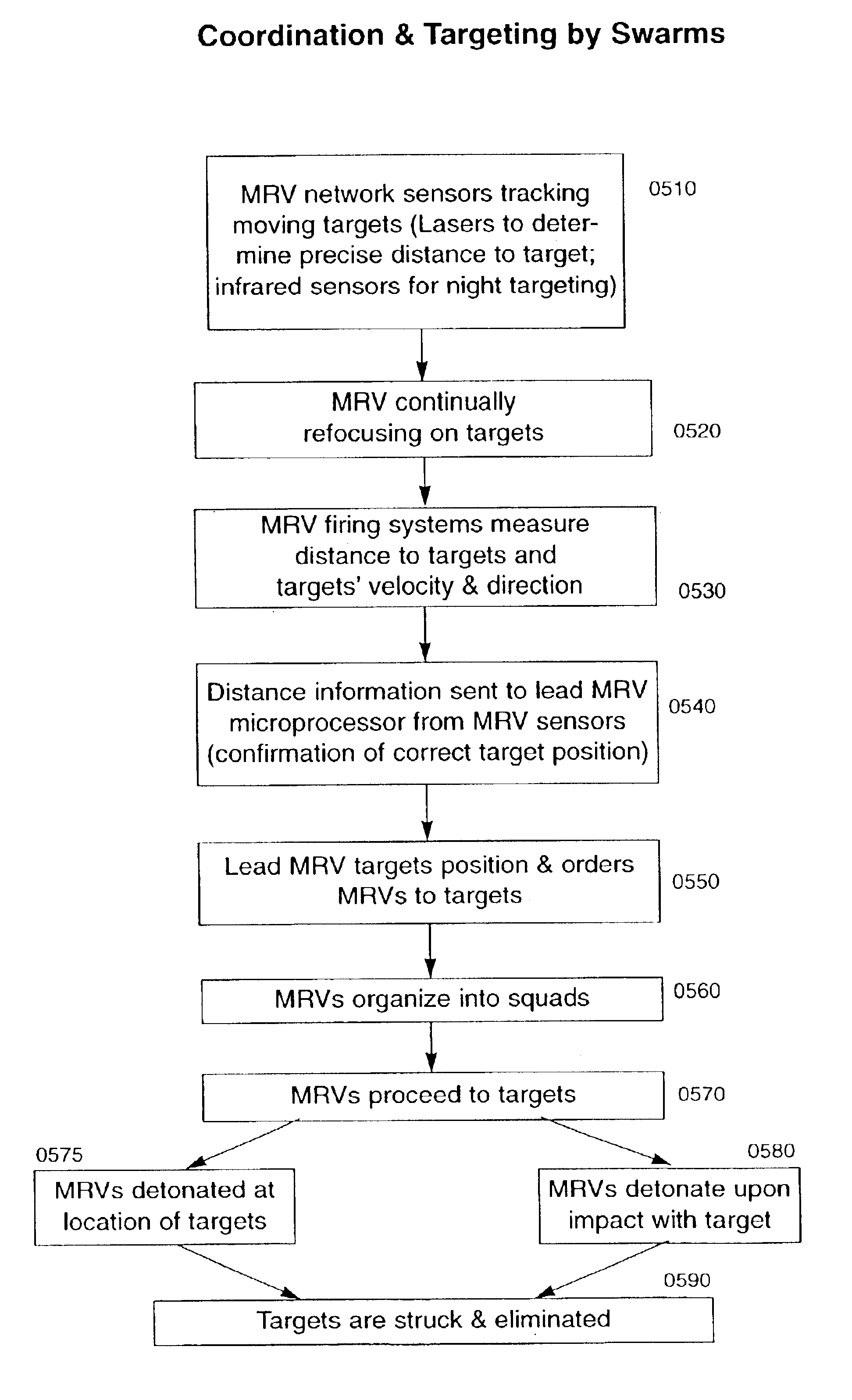
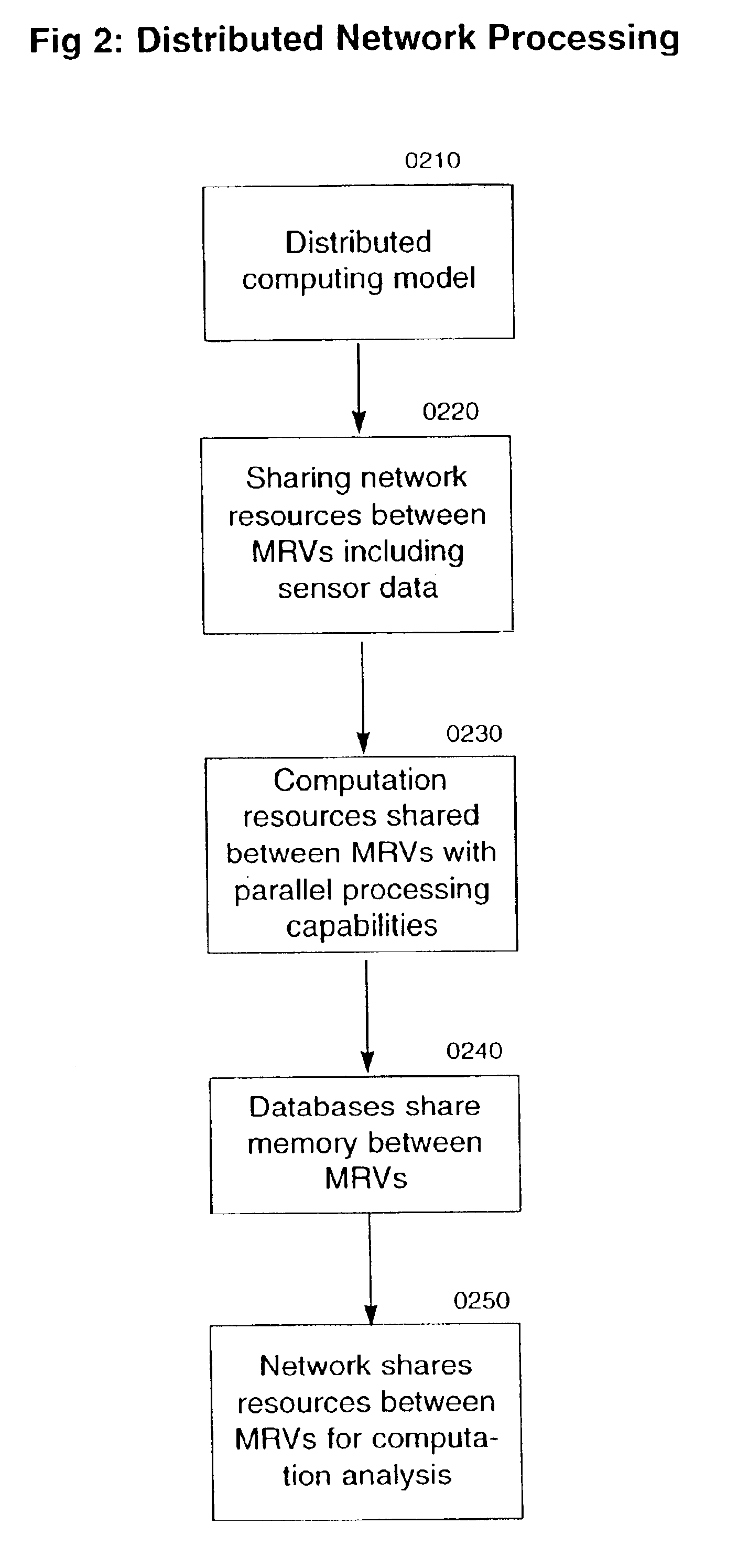
The system and methods incorporated in the present invention are implemented by using software program code applied to networks of computers. Specifically, the present invention represents a multirobotic system (MRS) that includes at least two mobile robotic agents. These robotic agents, mobile robotic vehicles (MRVs), have various useful purposes in the context of specific military applications. The MRVs use complex software program code, including mobile software agents, to execute specific instructions involving robotic and computational operations. The software capabilities activate specific robotic functions within MRVs involving movement and decision-making.

The present invention focuses on how groups of MRVs operate in a MRS. As such, the invention, or cluster of methods, solves...


PUM


Abstract

In a swarm weapon system, decision-making processes are described for the organization of mobile robotic vehicles (MRVs). After MRV drone sensor data is provided to a lead MRV, an initial decision is made by the lead MRV as a result of the selection of a winning simulation that provides the best opportunity for success of a mission. Once this decision is made, actions are organized for the MRVs, which provide feedback for the continuation of the process until the mission is completed.

Description

BACKGROUND OF THE INVENTIONThe U.S. Military has several fundamental strategic problems. First, the Army, Navy, Marines and Air Force have very large tactical systems and very small arms systems, on either extreme of the tactical spectrum, but hardly any weapon system in the middle sphere. Second, there is a great need to figure out how to develop automated tactical weapons systems that are powerful, effective, cost-effective and minimize casualties to our military personnel and to friendly noncombatants. Finally, the problem exists of how to organize and coordinate automated weapons to work in a coherent integrated systems structure. The swarm weapon system is intended to address these important challenges.One of the most extraordinary revolutions in advanced warfare in the last generation consists in the increasing automation of weapons systems. From Vietnam to the Gulf War and from Kosovo to Afghanistan and Iraq, the U.S. military has continued to enhance and rely on automated sy...

Claims


Application Information

Patent Timeline
IPC IPC(8): B64C39/00B64C39/02F41H13/00G05D1/02G05D1/10G06F19/00
CPCB64C39/024F41H13/00H04L67/12H04B7/18517G05D1/0088
Inventor SOLOMON, NEAL
Owner SOLOMON RES
Learn More