
Digital data storage subsystem including arrangement for increasing cache memory addressability

a technology of cache memory and addressability, applied in the field of digital computer systems, can solve problems such as the bottleneck of mass storage subsystem performance of cach

Inactive Publication Date: 2005-01-11
EMC CORP
View PDF2 Cites 16 Cited by
  • Summary
  • Abstract
  • Description
  • Claims
  • Application Information

AI Technical Summary

Benefits of technology

The invention provides a new and improved mass digital data storage subsystem that includes an arrangement for increasing cache memory addressability.
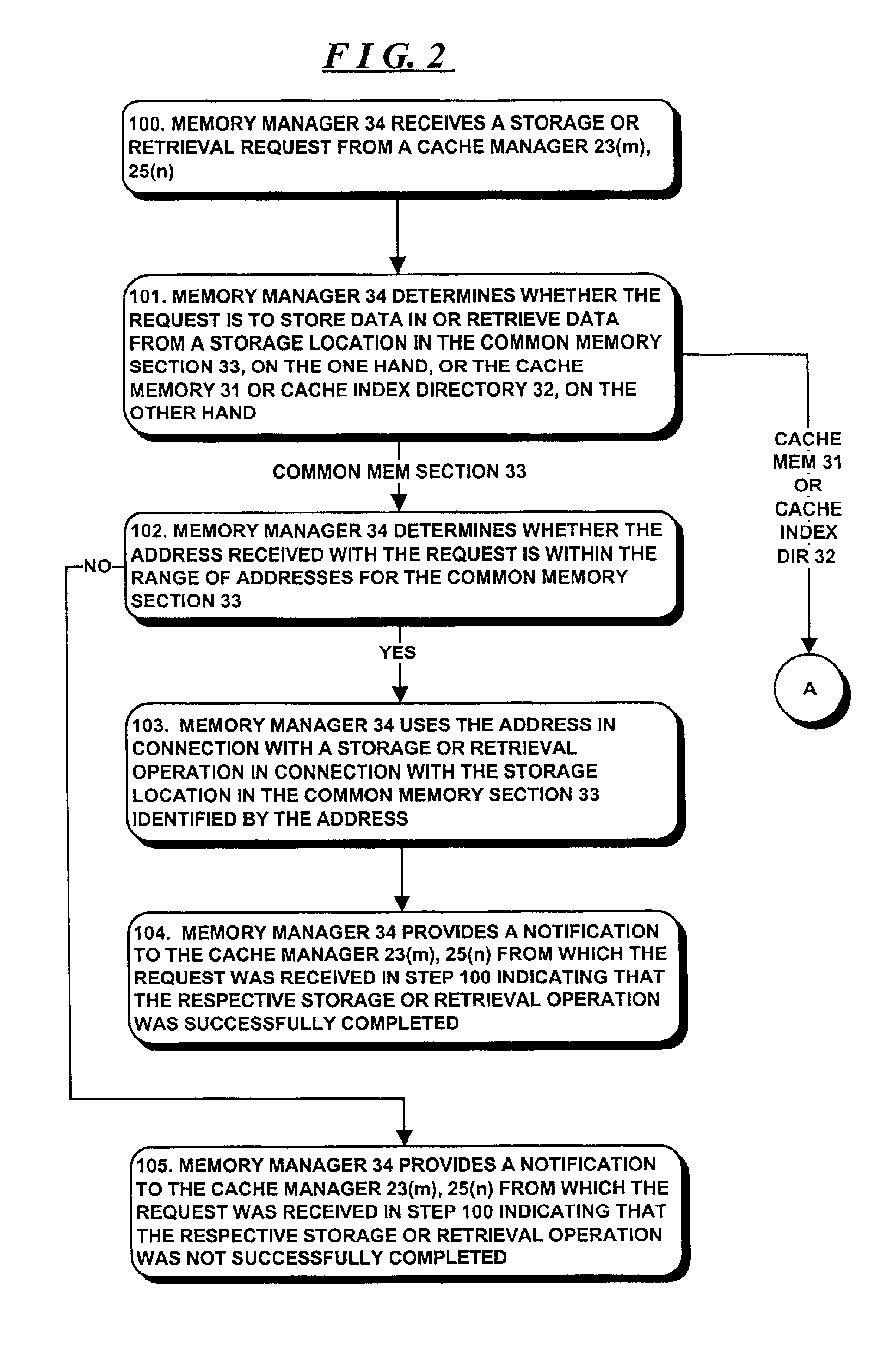
In one embodiment, the memory manager is used in connection with a large memory that is divided into a plurality of sections. One of the sections is a common memory that can be accessed by a number of elements using an absolute address. Another of the sections is in the form of a cache memory divided into a plurality of cache slots, with each cache slot having a plurality of storage locations. In an access request that requests access to a storage location in a cache slot, the segment identifier identifies the cache slot and the offset identifies the storage location in the cache slot that is to be accessed. In that embodiment, the memory manager generates an absolute address by shifting the bits comprising the cache slot identifier to higher-order bit positions and adding the offset thereto. This allows for addressing of larger cache memories.

Problems solved by technology

If these elements are not increased, the cache may become a bottleneck to performance of the mass storage subsystem.
A problem arises, however, in that typically, the word size that is used by many processing devices and systems is on the order of thirty-two bits, which would limit addressing of the memory used for the cache, directory table and so forth to four gigabytes (232 bytes).

Method used


Image

  • Digital data storage subsystem including arrangement for increasing cache memory addressability
  • Digital data storage subsystem including arrangement for increasing cache memory addressability
  • Digital data storage subsystem including arrangement for increasing cache memory addressability

Examples


Embodiment Construction

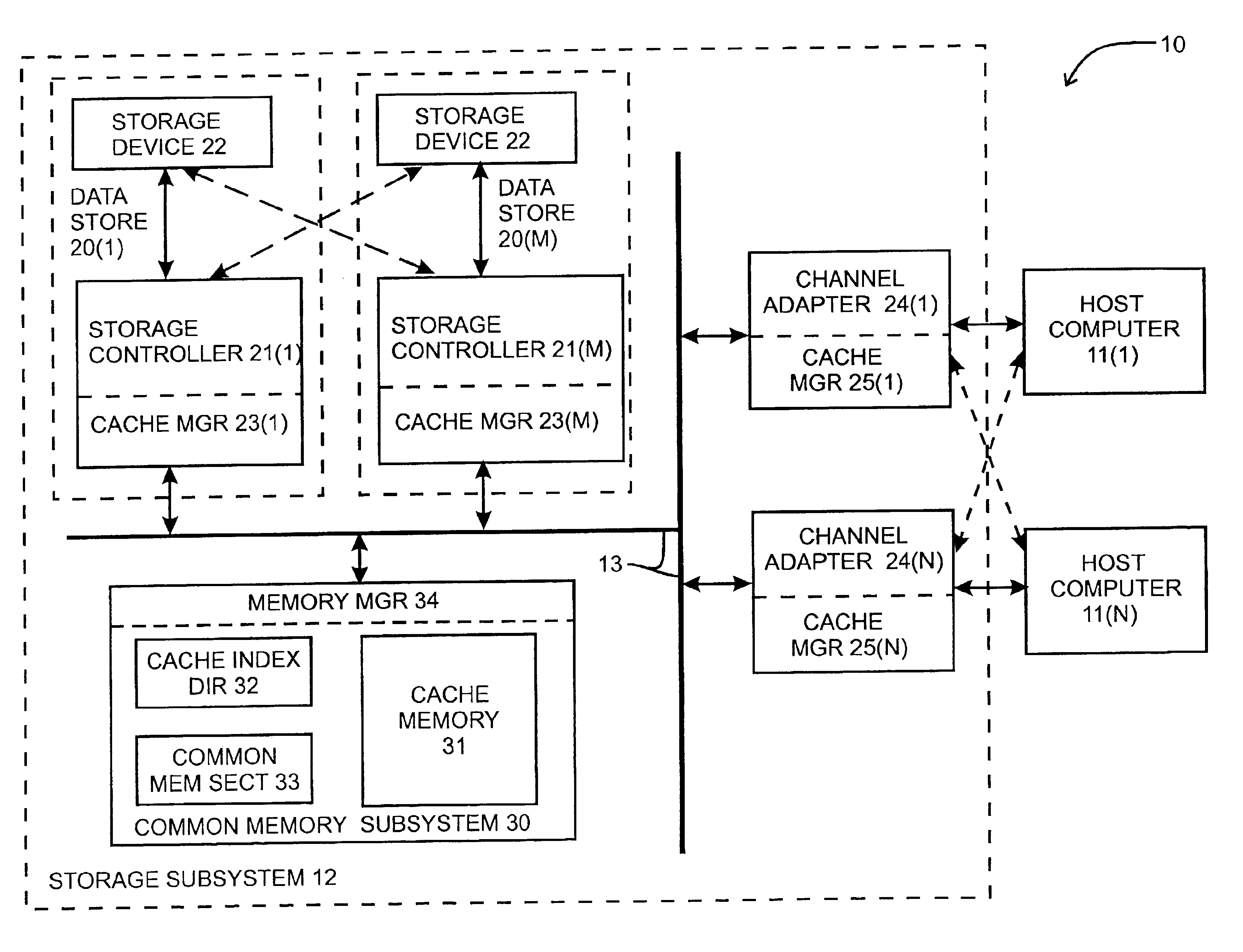
The invention will be described in connection with a digital computer system 10 depicted in functional block diagram form in FIG. 1. With reference to FIG. 1, computer system 10 includes a plurality of host computers 11(1) through 11(N) (generally identified by reference numeral 11(n)) and a digital data storage subsystem 12 interconnected by a common bus 13. Each host computer 11(n) may comprise, for example, a personal computer, workstation, or the like which may be used by a single operator, or a multi-user computer system which may be used by a number of operators. Each host computer 11(n) is connected to an associated channel adapter 24(n), which, in turn, is connected to bus 13. Each host computer 11(n) may control its associated channel adapter 24(n) to perform a retrieval operation, in which the channel adapter 24(n) initiates retrieval of computer programs and digital data (generally, “information”) from the digital data storage subsystem 12 for use by the host computer 11(...


PUM


Abstract

A memory manager for use in connection with a memory comprises a memory access request receiver module, an address translation module and a memory access operation control module. The memory access request receiver module is configured to receive an access request requesting an access operation in connection with the memory, the access request including an address. The address translation module is configured to, (i) if the access request requests an access operation in connection with one of a plurality of sections of the memory, provide the address in the access request as an absolute address identifying at least one storage location in the one section; and (ii) if the access request requests an access operation in connection with another of said sections, generate an absolute address from the address provided in the access request, the address in the access request including a segment identifier and an offset, the address translation module being configured to process the segment identifier and offset to generate an absolute address identifying at least one storage location in the other of said sections. The memory access operation control module is configured to perform an access operation in connection with the memory using the absolute address generated by the address translation module.

Description

FIELD OF THE INVENTIONThe invention relates generally to the field of digital computer systems and more particularly to a digital data storage subsystem including an arrangement for increasing cache memory addressability.BACKGROUND OF THE INVENTIONIn modern “enterprise” computing environments, that is, computer systems for use in an office environment in a company, a number of personal computers, workstations, mini-computers and mainframe computers, along with other devices such as large mass storage subsystems, network printers and interfaces to the public telephony system, may be interconnected to provide an integrated environment in which information may be shared among users in the company. Typically, users may be performing a variety of operations, including order receipt, manufacturing, shipping, billing, inventory control, and other operations, in which sharing of data on a real-time basis may provide a significant advantage over, for example, maintaining separate records and...

Claims


Application Information

Patent Timeline
Patent Type & Authority Patents(United States)
IPC IPC(8): G06F12/08
CPCG06F12/0866G06F2212/261
Inventor VISHLITZKY, NATANKOPYLOVITZ, HAIMSHAGAM, ELI
Owner EMC CORP
Learn More