Automatic system for collecting, weighing and releasing solid particles

a technology of automatic system and solid particle collection, which is applied in the direction of liquid/fluent solid measurement, volume measurement, volume measurement, etc., can solve the problems of not being very precise and accurate, measuring system, and length of sampling time,

Inactive Publication Date: 2005-01-18
ING ENERGETICA Y DE CONTAMINACION
View PDF3 Cites 23 Cited by
  • Summary
  • Abstract
  • Description
  • Claims
  • Application Information

AI Technical Summary

Benefits of technology

The system to be patented may be integrated in automatic particle sampling equipment based on any of these international standards, making up a system which makes it possible to carry out continuously measurement of the mass flow of solids transported pneumatically through a transport duct.
It needs no calibration using comparative measurements. Non-extractive measuring equipment carries out indirect measuring which is related to the particle flow through laborious calibrations using manual reference systems. In this aspect, the system described, associated with automatic portable sampling equipment, makes it possible the automatic execution of calibration routines for these measuring systems.

Problems solved by technology

The advantage of this method, in comparison to the others, is that it aspirates isokinetically at all points of the section, and its main disadvantage is the length of time needed for the sampling.
The disadvantage of this system is that it produces results by indirect measurement of the weight of the particles by determining the volume of the sample.
This may give rise to significant errors in the case of changes in the density of the solid or distribution of the size of particles, requiring continuous adjustment of the equipment to guarantee the quality of the measurement.
These measurement systems have the disadvantage of not being very precise and accurate, due to the fact that they are sensitive to parameters such as the humidity content of the mixture, the size of particles and the phenomena of segregation in the ducts.
In addition, they require periodic calibration using comparative measurements carried out using extractive methods, and do not allow for the obtention of a sample for later laboratory analysis.
However, these devices, in addition to having other aims, lack, among others, the characteristics related to the particle expulsion system.
All of this means that at present none of these technologies has reached a sufficiently robust state for large-scale industrial implementation.

Method used


Image

  • Automatic system for collecting, weighing and releasing solid particles
  • Automatic system for collecting, weighing and releasing solid particles
  • Automatic system for collecting, weighing and releasing solid particles

Examples


Embodiment Construction

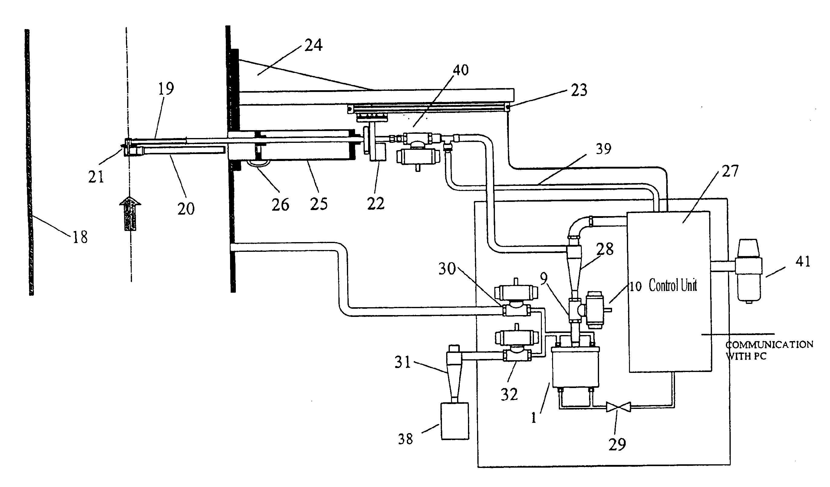
The solid particle capture, weighing, and expulsion system consists of a weighing chamber (1) made up of a cylindrical outer container (2) and a screw lid (3). The lid (3) has a particle entrance duct (4); the particles enter the chamber (1) by gravity and are collected in a container (5) which is also cylindrical with an exterior diameter two millimetres less than the internal walls of the container (2). The container (5) has a conical base to facilitate the elimination of the particles, and is joined to a platform (6) attached by screws to a load cell (7) on the base of the container (2) and supported above it by two screws. In this way the weight of the sample is transmitted to the load cell (7) as the sample is collected.

The arrangement of the container (5) inside the chamber (1) composed of parts (2) and (3) is concentric to these, and so between the container (2) and the container (5) there is a one millimeter space in the form of a circular corona. The height of the container...


PUM


Abstract

A automatic system for the capture, weighing and expulsion of solid particles, consisting of an airtight weighing chamber, inside which there is an inner container in which the particles entering the chamber through an entrance duct are collected. Said container transmits its weight to a weighing sensor, also located inside the weighing chamber but not in contact with the walls of the chamber. Once weighed, the sample is expelled from the chamber by the injection of compressed air. The system can be directly applied to determine the mass flow of solid particles in pneumatic transport ducts by integrating it into automatic sampling systems, and also gives a signal which can be integrated in regulating loops for the control of said flow.

Description

BACKGROUND OF THE INVENTION1. Field of InventionThere are numerous industrial processes which require the transport of solids through ducts using a carrier gas steam. Examples are the food industry, the pharmaceutical industry and, especially, combustion processes using solid fuel, such as power plants, cement factories and blast furnaces.Although for gases and liquids there has traditionally been a wide variety of equipment for continuous measurement of the mass flow through ducts, in the case of pneumatically transported solids, it is only in recent years that promising technologies have been developed for determining this parameter.The importance of measuring the mass flow of solids depends on the particular process involved. For coal-fired power stations this measurement is of vital importance from the point of view of the performance and operation of the plant and the emission of pollutants.Most coal-fired power stations use direct fuel feed systems. In these systems, the coal ...

Claims


Application Information

Patent Timeline
Patent Type & Authority Patents(United States)
IPC IPC(8): G01F1/74
CPCG01F1/74
Inventor AGUILERA, MANOLO CONSTANTINOBAREA, FRANCISCO RODRIQUEZLOZANO, MIGUEL ANGEL DELGADOHOLGADO, ENRIQUE TOVA
Owner ING ENERGETICA Y DE CONTAMINACION
Why Eureka
Try Eureka