Fuel tank pressure control valve including an integrated sensor

a technology of pressure control valve and fuel tank, which is applied in the direction of valve operating means/releasing devices, functional valve types, machines/engines, etc., can solve the problems of temperature and age change of pressure blow-off level, orifice structure cannot be used anymore, and diaphragm-actuated valves cannot be used

Inactive Publication Date: 2005-01-18
SIEMENS VDO AUTOMOTIVE CORP
View PDF18 Cites 32 Cited by
  • Summary
  • Abstract
  • Description
  • Claims
  • Application Information

AI Technical Summary

Benefits of technology

FIG. 1 is a sectional view of a fuel tank pressure control valve in a first configuration wherein fluid flow is permi

Problems solved by technology

It is believed that such orifice structures could no longer be used with the advent of requirements controlling on-board refueling.
It is believed that these diaphragm-actuated valves suffer from a number of disadvantages including that the calibration (i.e., pres

Method used


Image

  • Fuel tank pressure control valve including an integrated sensor
  • Fuel tank pressure control valve including an integrated sensor
  • Fuel tank pressure control valve including an integrated sensor

Examples


Embodiment Construction

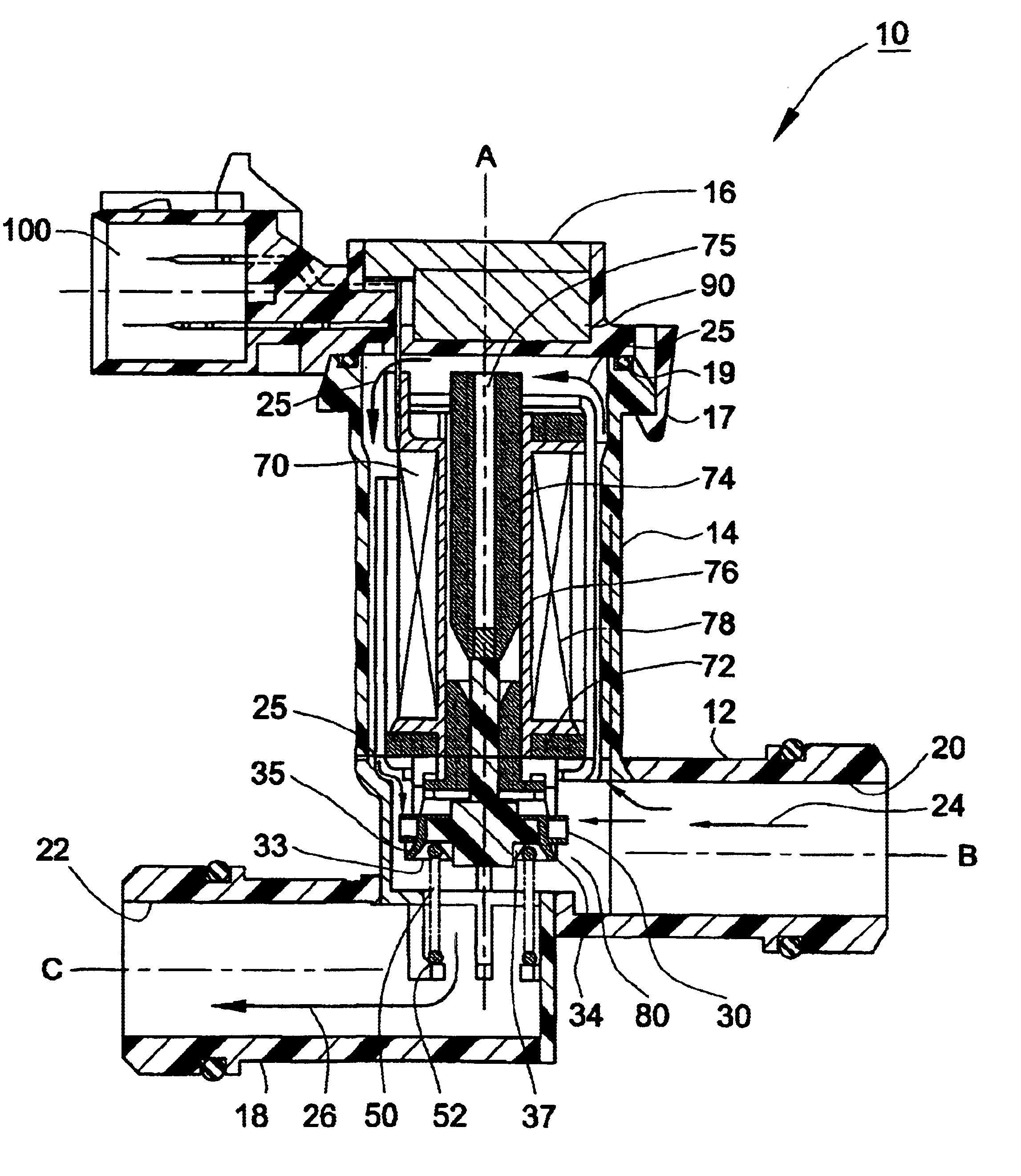
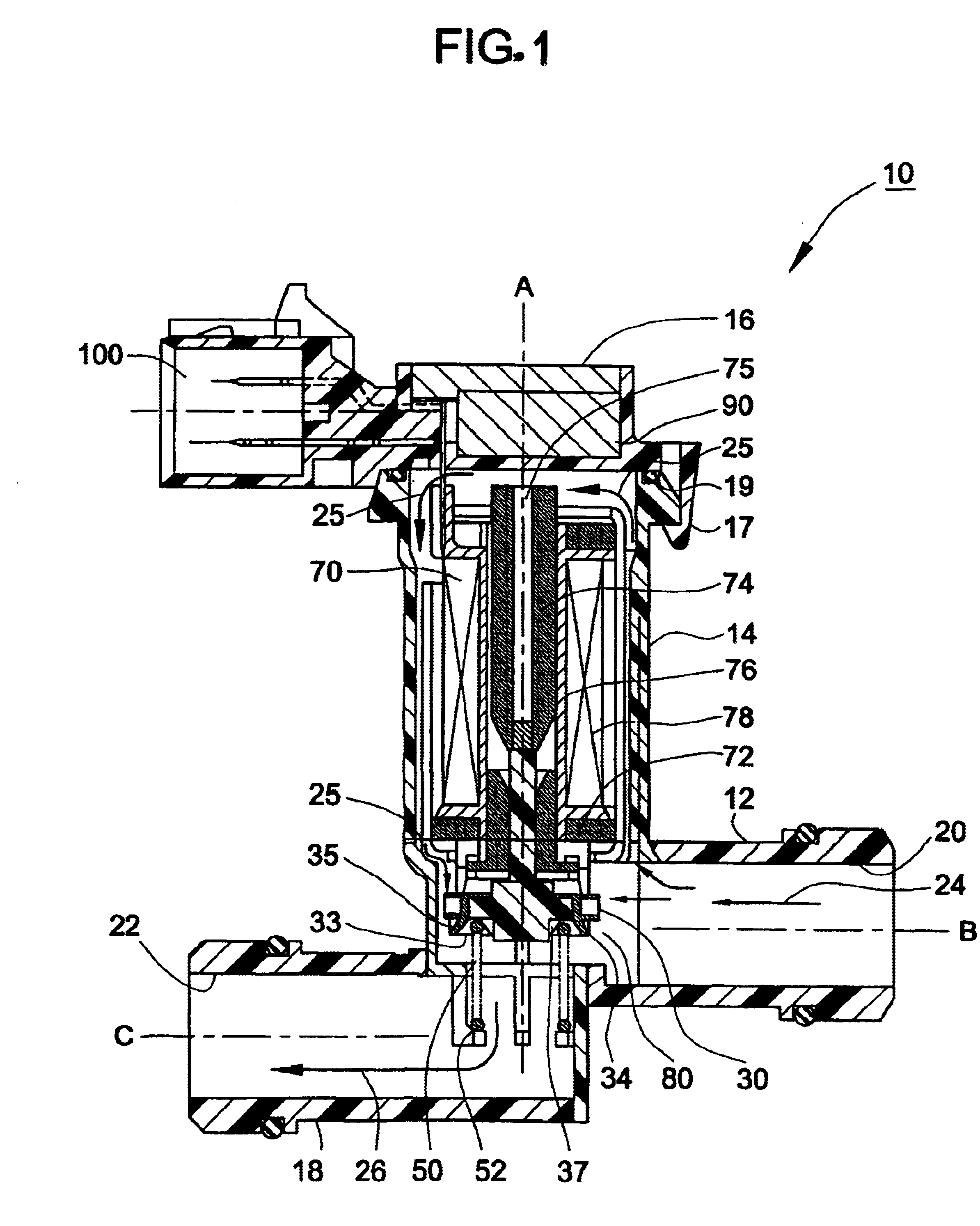
A fuel tank pressure control valve 10 can be located along a vapor line (not shown) connecting a fuel vapor dome, i.e., the gaseous portion within a fuel tank (not shown), and a charcoal canister (not shown). A canister purge control valve (not shown) can be used to purge hydrocarbons that have been collected in the charcoal canister (not shown). Typically, the hydrocarbons that are purged from the charcoal canister are combusted by an internal combustion engine (not shown).

A vapor dome pressure level that is approximately 10″ water above atmospheric pressure has been determined to suppress fuel vapor generation in the fuel tank (not shown). A fuel tank pressure sensor (not shown) can be used to detect pressures in excess of this determined level. When excess pressure is detected, the fuel tank pressure control valve 10 is supplied an electrical signal, which results in the fuel tank pressure control valve 10 opening to decrease pressure to or slightly below the determined level.

The...


PUM


Abstract

A device for controlling fluid flow between an evaporative emission space of a fuel tank and a fuel vapor collection canister that includes a housing, a valve, a seal, an electric actuator, an electric transducer, and an electrical connector. The housing includes a first port, a second port, and a fluid flow path that extends between the first and second ports. The first port is adapted for receiving fluid flow from the evaporative emission space and is at a first pressure level. The second port is adapted for supplying fluid flow to the fuel vapor collection canister and is at a second pressure level. The valve is movable along an axis with respect to the housing between a first configuration, a second configuration, and an intermediate configuration between the first and second configurations. The first configuration permits substantially unrestricted fluid flow between the first and second ports. The second configuration prevents fluid flow between the first and second ports. The seal is located at an interface between the housing and the valve and includes an annular lip, which projects obliquely with respect to the axis in the first configuration of the valve. The electric actuator is disposed within the housing and is operatively coupled to the valve element. The electric transducer is disposed within the housing and is in fluid communication with the fluid flow path. The electric transducer senses the first pressure level. The electrical connector is disposed on the housing. The electrical connector includes a first set of terminals, which are in electrical communication with the electric actuator and a second set of terminals, which are in electrical communication with the electric transducer.

Description

FIELD OF THE INVENTIONThis disclosure generally relates to a pressure control valve. In particular, this disclosure is directed to an electrically operated valve, including an integrated sensor and common electrical connector, to control the level of vapor pressure in a fuel tank of a vehicle.BACKGROUND OF THE INVENTIONIt is believed that prior to legislation requiring vehicles to store hydrocarbon vapors that are generated when refueling a vehicle, a simple orifice structure was used to maintain a positive pressure in a fuel tank to retard vapor generation. It is believed that such orifice structures could no longer be used with the advent of requirements controlling on-board refueling. It is believed that, on some vehicles, the orifice structure was simply deleted, and on other vehicles, the orifice structure was replaced with a diaphragm-actuated pressure relief valve. It is believed that these diaphragm-actuated valves suffer from a number of disadvantages including that the cal...

Claims


Application Information

Patent Timeline
IPC IPC(8): F16K31/06F16K24/04F16K24/00
CPCF16K31/0655F16K24/04Y10T137/7761Y10T137/7771Y10T137/8326Y10T137/86324Y10T137/8704
Inventor WELDON, CRAIGBALSDON, DAVID W.PARABDESAI, SUDHIR
Owner SIEMENS VDO AUTOMOTIVE CORP
Why Eureka
Try Eureka