Flexible track drilling machine

a flexible track and drilling machine technology, applied in the direction of computer control, program control, instruments, etc., can solve the problems of inability to lay a pair of straight lines, inability to precisely the same distance apart of flexible rails at all points along the rails, and high cost of machines to procure and operate. , to achieve the effect of reducing the pre-load for

Inactive Publication Date: 2005-01-18
THE BOEING CO
View PDF13 Cites 119 Cited by
  • Summary
  • Abstract
  • Description
  • Claims
  • Application Information

AI Technical Summary

Benefits of technology

The X-axis drive device preferably employs a pinion gear mounted on one cantilevered end of the plate-shaped spring that is disposed above one of the rails (i.e., the reference rail). The pinion gear engages a rack mounted on the reference rail. To control the height of the pinion gear relative to the rack so that the height is substantially constant as the X-axis carriage is driven along the reference rail, the rotational axis of the pinion gear preferably lies in the same plane as the rotational axes of a pair of rollers mounted on the end of the spring. The rollers preferably are V-groove rollers that define V-shaped grooves in which the opposite edges of the rail are engaged, thus preventing movement of the rollers relative to the rail in the direction generally normal to the workpiece surface.
In a preferred embodiment of a fle

Problems solved by technology

The problem of accurately drilling holes in large workpieces such as aircraft wing and fuselage panels and other types of structures has been an ongoing challenge in the aircraft industry as well as other industries, and one for which a completely satisfactory solution applicable to a wide range of workpiece configurations has not heretofore been provided.
Large fixed-monument machines such as five-axis drilling machines can be used for some types of workpieces, but these machines are quite expensive to procure and operate.
On such a compound-contoured surface,

Method used


Image

  • Flexible track drilling machine
  • Flexible track drilling machine
  • Flexible track drilling machine

Examples


Embodiment Construction

The present invention now will be described more fully hereinafter with reference to the accompanying drawings, in which preferred embodiments of the invention are shown. This invention may, however, be embodied in many different forms and should not be construed as limited to the embodiments set forth herein; rather, these embodiments are provided so that this disclosure will be thorough and complete, and will fully convey the scope of the invention to those skilled in the art. Like numbers refer to like elements throughout.

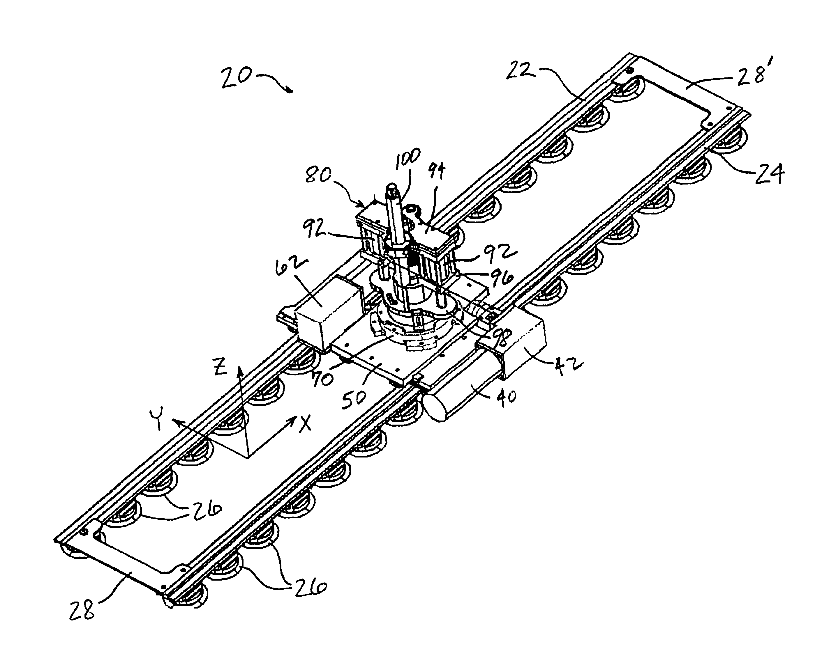
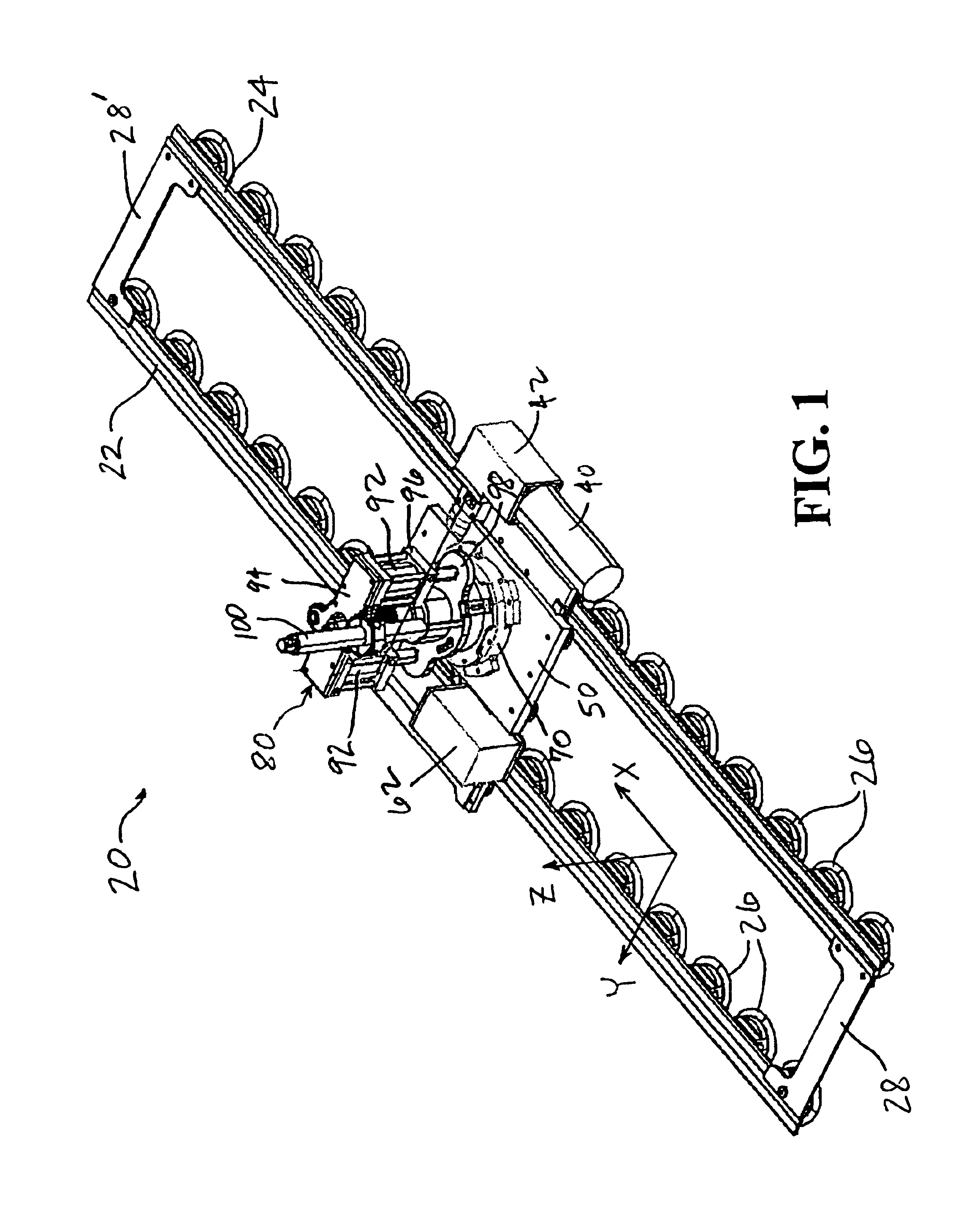
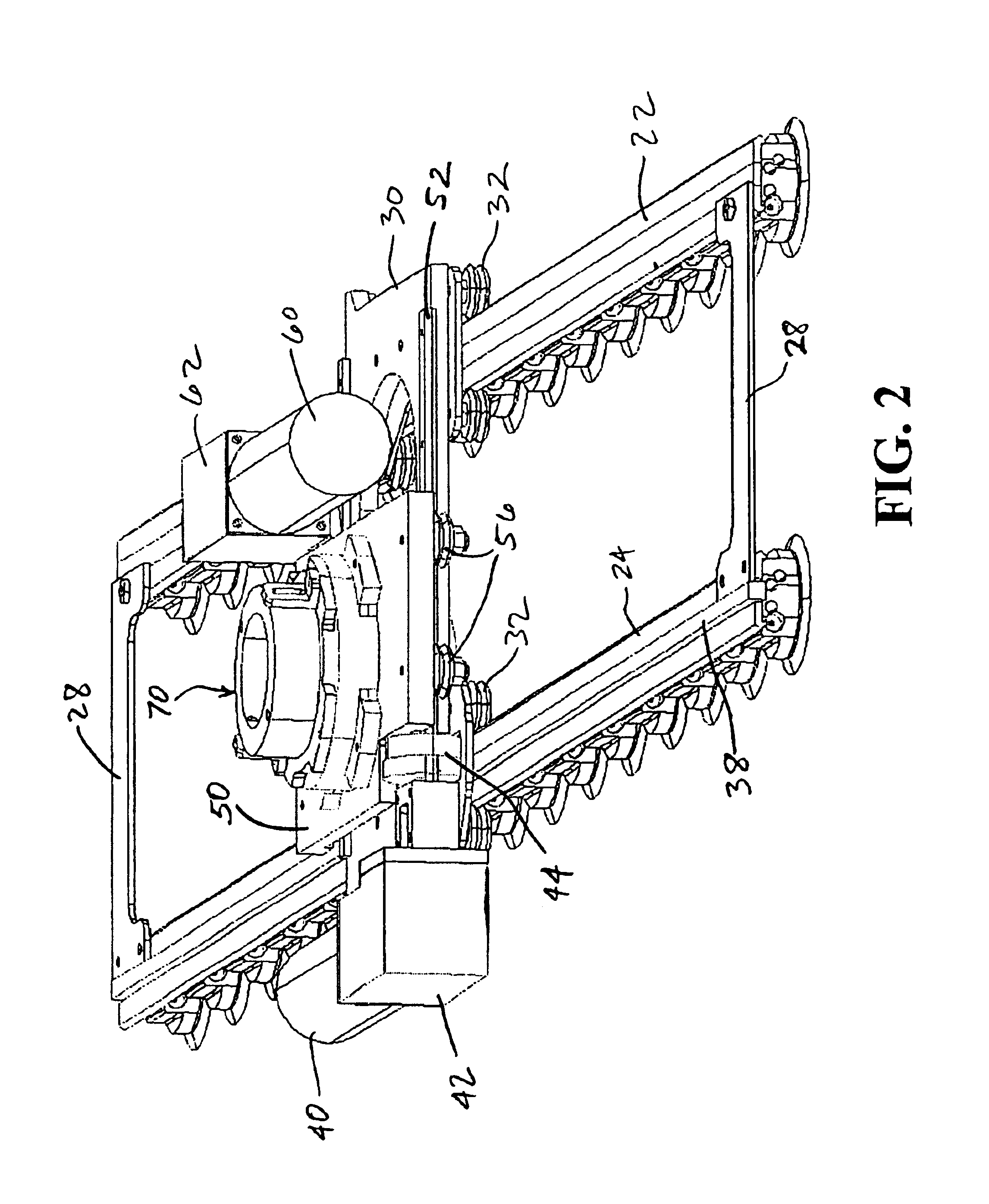
With reference to FIG. 1, a machine 20 in accordance with one preferred embodiment of the invention is shown. The machine comprises a pair of rails 22, 24 to which a plurality of attachment devices, preferably in the form of vacuum cup assemblies 26, are releasably affixed at spaced intervals along the length of each rail. The rails 22, 24 preferably have a width substantially greater than their thickness such that they are substantially stiffer in bending about...


PUM

PropertyMeasurementUnit
Flexibilityaaaaaaaaaa
Distanceaaaaaaaaaa

Abstract

A flexible track drilling machine employs a pair of rails that are flexible in one direction to conform to a non-flat workpiece surface and are substantially stiff in a direction parallel to the workpiece surface. The rails are attached to the workpiece by vacuum cups spaced along each rail. An X-axis carriage is slidably mounted on the rails by rollers mounted on flexible spring plates affixed to the carriage. A drill or other device to be positioned is mounted on a Y-axis carriage that is slidably connected to the X-axis carriage. The three-dimensional surface of the workpiece is mathematically transformed into a two-dimensional flat pattern, and the positioning of the carriages is controlled based on the flat pattern.

Description

FIELD OF THE INVENTIONThe present invention relates to machines for drilling or performing other work operations on large workpieces configured as simple- or compound-contoured panels or the like, such as wing and fuselage sections for aircraft. The invention relates more particularly to a flexible track machine and method for positioning a working module such as a drill, marking device, or the like, relative to a workpiece by traversing the module along a track mounted on and indexed to the workpiece.BACKGROUND OF THE INVENTIONThe problem of accurately drilling holes in large workpieces such as aircraft wing and fuselage panels and other types of structures has been an ongoing challenge in the aircraft industry as well as other industries, and one for which a completely satisfactory solution applicable to a wide range of workpiece configurations has not heretofore been provided. Large fixed-monument machines such as five-axis drilling machines can be used for some types of workpiec...

Claims


Application Information

Patent Timeline
IPC IPC(8): B23Q1/26B23Q9/00B23Q1/62G05B19/408
CPCB23Q1/26B23Q9/0007B23Q1/621Y10T409/306384
Inventor BOYL-DAVIS, THEODORE MARTINBUTTRICK, JR., JAMES N.GAGE, ROGER A.JONES, DARRELL D.PAPANIKOLAOU, KOSTANDINOS D.
Owner THE BOEING CO
Why Eureka
Try Eureka