Air diffuser and flushing method thereof

Inactive Publication Date: 2005-01-18
KUBOTA LTD
View PDF10 Cites 6 Cited by
  • Summary
  • Abstract
  • Description
  • Claims
  • Application Information

AI Technical Summary

Benefits of technology

With this construction, the control means can switch air diffusion operation and flushing operation by opening/closing the flushing valve. At such a particular time that the amount of waste water flowing to the tank is below the predetermined value, flushing operation can be performed automatically. Flushing operation performed at that particular time prevents excessive air diffusion and also performs flushing of the diffuser tube. Further, even if a slight flow of waste water continues for a long period of time, the intra-tank mixed liquor is stirred in the ai

Problems solved by technology

On the other hand, the local area of the filtration membranes 53 receiving less air fails to obtain a sufficient flushing effect, which accelerates the attachment of cake to the membrane surfaces.
With this air diffuser, it is however difficult to completely avoid that the blowholes and a diffuser tube become clogged by activated sludge.
When the air diffuser becomes clogged, it is difficult to perform biological treatment with activated sludge.
This impairs the function of the membrane separator.
The amount of waste water flowing to the waste water treatment facility is not always constant.
That is, the fac

Method used


Image

  • Air diffuser and flushing method thereof
  • Air diffuser and flushing method thereof
  • Air diffuser and flushing method thereof

Examples


Example

First Preferred Embodiment

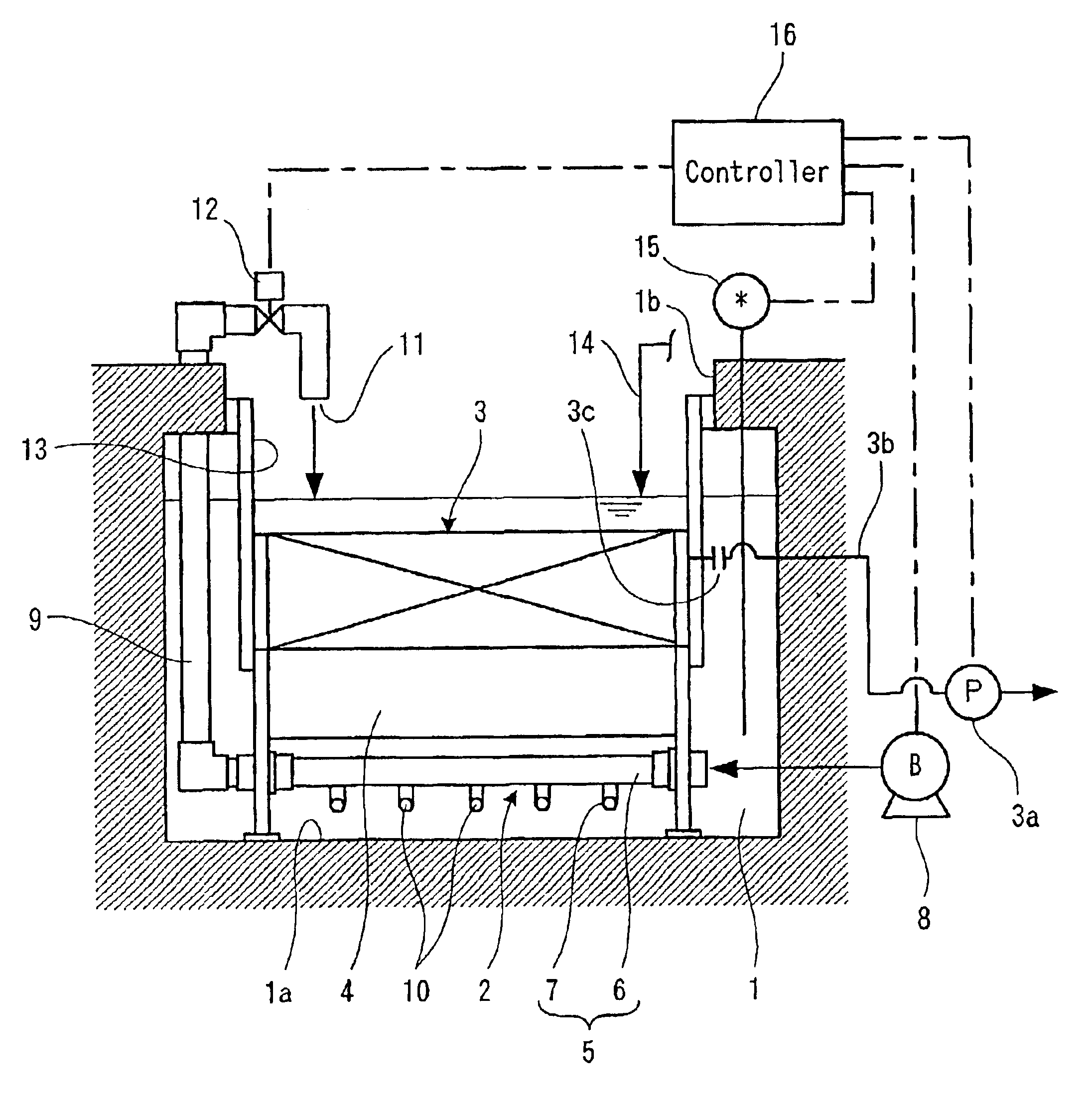
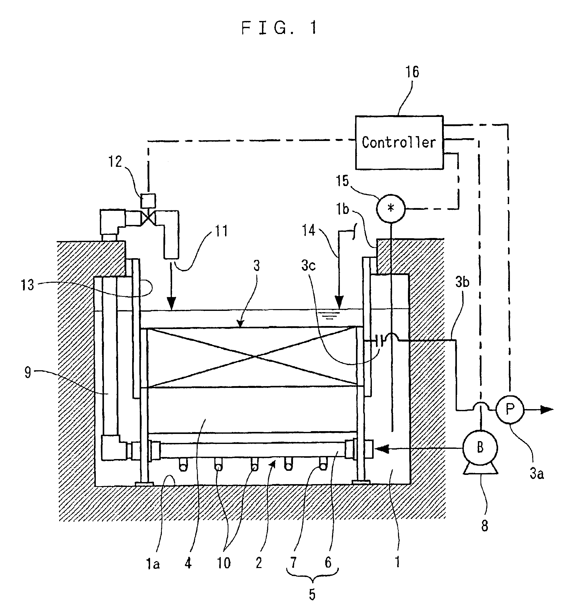
A first preferred embodiment will be described below based on the accompanying drawings. Referring to FIGS. 1 to 3, an air diffuser 2 and a membrane separator 3 disposed above the air diffuser 2 are immersed in an aeration tank 1 for performing membrane separation activated sludge treatment. A variety of separation membranes, such as organic flat membrane type, tube type and ceramic type, are usable for the membrane separator 3. Hereat, there are used a plurality of membrane cartridges using organic flat membrane type separation membrane (filtration membrane), as shown in FIG. 1. The membrane cartridges are oriented vertically and in parallel with each other at predetermined spaced intervals to form a passage between the adjacent membrane cartridges. The membrane separator 3 is removably connected via a coupling 3c to a passage 3b provided with a suction pump 3a, and is activated by a pump suction pressure as a driving pressure. As the driving pressure, the...


PUM

PropertyMeasurementUnit
Timeaaaaaaaaaa
Pressureaaaaaaaaaa

Abstract

An air diffuser (2) having a diffuser tube (5) immersed sidewardly in a tank (1), a flushing pipe (9) opening at its tip an outlet (11) at an upper position of the diffuser tube, and a flushing valve (12) disposed in the flushing pipe (9). The diffuser tube (5) is made up of a main pipe (6) communicated at its basal end to an air supply source (8) and communicated at its tip to the flushing pipe (9), and a plurality of branch pipes (7) being communicated to the main pipe (6) and opening at their tip as a blowhole (10) at a lower position of the main pipe (6). During air diffusion, air is supplied from the air supply source (8) with tile flushing valve (12) closed, and the air is diffused from the blowholes (10). During flushing, air is supplied from the air supply source (8) with the flushing valve (12) opened and an intra-tank mixed liquor is sucked from the openings of the diffuser tube (5), thereby flushing the inside of the diffuser tube (5) with the sucked intra-tank mixed liquor. The intra-tank mixed liquor is then joined with air to come off together from the outlet (11) of the flushing pipe (9). Air diffusion from the blowholes (10) and the flushing of the diffuser tube (5) are alternately repeated by utilizing pulsation to be caused by pressure variations in the diffuser tube (5).

Description

TECHNICAL FIELDThe present invention relates to an air diffuser and a method of flushing an air diffuser and, in particular, to techniques of aerating an intra-tank mixed liquor in membrane separation activated sludge process.BACKGROUND ARTMembrane separators used in membrane separation activated sludge process for biologically treating waste water, drainage water etc have a plurality of membrane cartridges. As shown in FIG. 11, a membrane cartridge 51 has filtration membranes 53 disposed on the front and rear surfaces of a filter supporting plate 52 made of resin, and the entire peripheral portions of the filtration membranes 53 are fused to the filter supporting plate 52 by heating with a heater or by ultrasonic vibration. A transmitted liquor passage is present between the filter supporting plate 52 and each filtration membrane 53. A collecting hole 54 communicated to the transmitted liquor passage extends from front to rear of the filter supporting plate 52. A transmitted liquor...

Claims


Application Information

Patent Timeline
IPC IPC(8): B01D65/08B01D63/08B01D61/18B01D65/00B01F13/00B01F3/04B01F13/02C02F3/12C02F3/20C02F1/44C02F3/30B01F15/00B01F33/40
CPCB01D61/18B01D65/08B01F3/04248B01F3/04262B01F3/04985B01F13/025C02F1/444C02F3/1273C02F3/20C02F3/302B01D63/082Y10S261/70B01D2321/185B01D2321/2066B01F15/00123B01F2003/04148B01F2003/04319B01F2003/04361C02F3/12Y02W10/10B01F23/23113B01F23/23121B01F23/231231B01F23/23123B01F23/231265B01F23/29B01F33/40512B01F35/20B01D63/0821
Inventor OKAJIMA, YASUNOBUUEJIMA, TATSUYANAGANO, MASAAKIIZUMI, KIYOSHI
Owner KUBOTA LTD
Why Eureka
Try Eureka