Sealing of nozzle slashfaces in a steam turbine

Inactive Publication Date: 2005-01-18
GENERAL ELECTRIC CO
View PDF19 Cites 26 Cited by
  • Summary
  • Abstract
  • Description
  • Claims
  • Application Information

AI Technical Summary

Benefits of technology

A particular advantage of the present invention resides in the ability to retrofit spline seals to existing steam turbines as a means of improving overall machine performance. To accomplish this, and during a normal outage for maintenance, the nozzle segments may be removed, i.e., rolled, from the turbine casing. Slots may be machined in the slashfaces to receive the spline seals. The segments are then rolled back into upper and lower casings with the spline seals inserted between opposing slashfaces, thereby reducing steam leakage paths in existing turbines after the retrofit.
In a preferred embodiment according to the present invention, there is provided a steam turbine comprising a rotor carrying a plurality of circumferentially spaced buckets and forming part of a stage of a steam turbine section, a stationary casing surrounding the rotor including a plurality of nozzle segments carrying a plurality of nozzles and forming another part of the stage of the steam turbine section, each of the segments having endfaces respectively in circumferential registry with opposed endfaces of circumferentially adjacent segments, each of the endfaces including at least a first slot opening in a general circumferential direction and in circumferential registration with the slot of circumferentially adjacent endfaces and a first spline seal extending between each of the adjacent endfaces of circumferentially adjacent segments and in the slots for minimizing or precluding steam leakage flow past the registering endfaces.
In a further preferred embodiment according to the present invention, there is provided a steam turbine comprising a plurality of circumferentially spaced buckets and forming part of a stage of a rotor carrying a s

Problems solved by technology

These slashface gaps can be sufficiently large to produce substantial leakage between the differential pressure regions forward and aft of the nozzles.
The problem is compounded due to the larger number of nozzle segments on a typical re

Method used


Image

  • Sealing of nozzle slashfaces in a steam turbine
  • Sealing of nozzle slashfaces in a steam turbine
  • Sealing of nozzle slashfaces in a steam turbine

Examples


Example

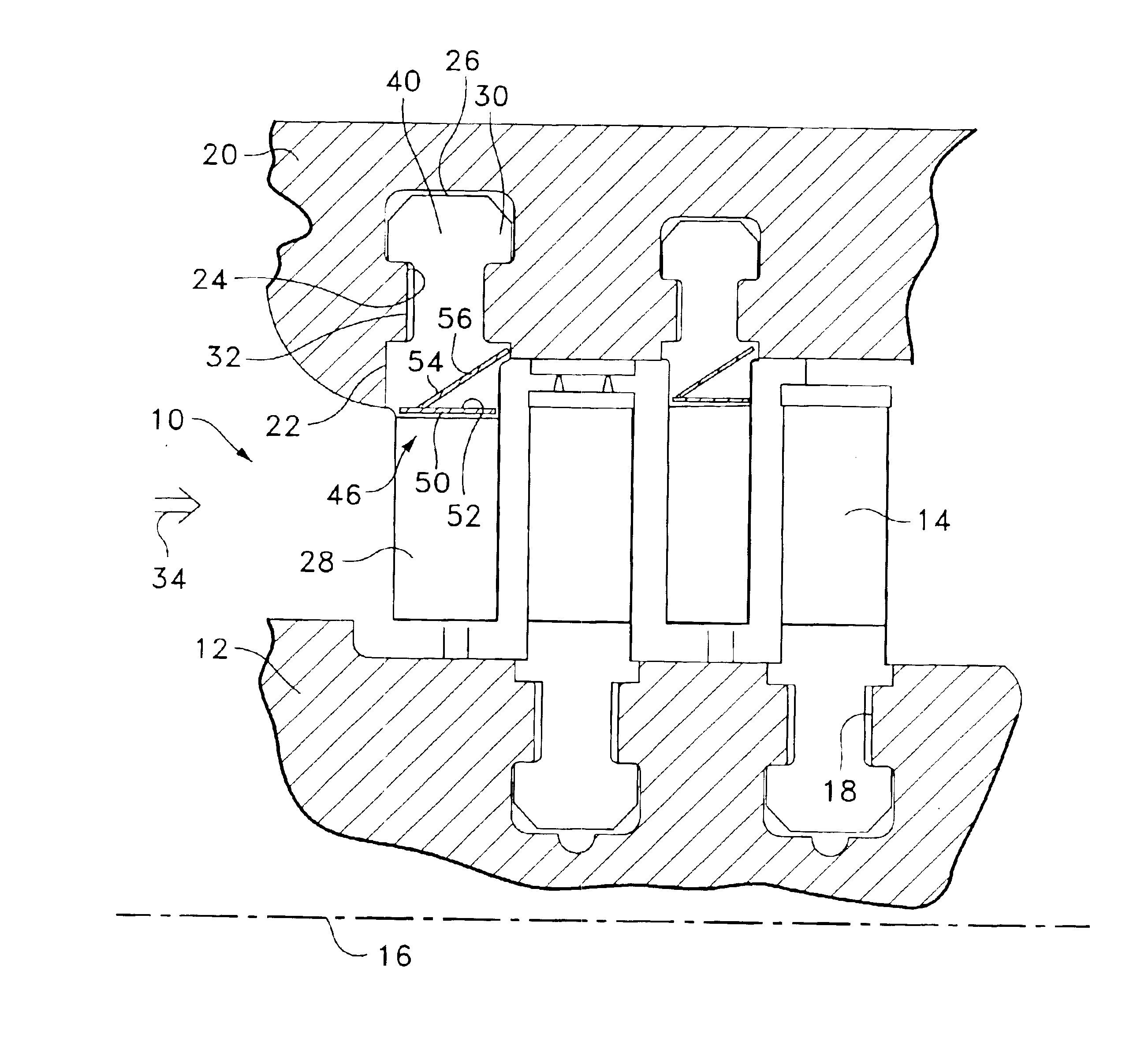
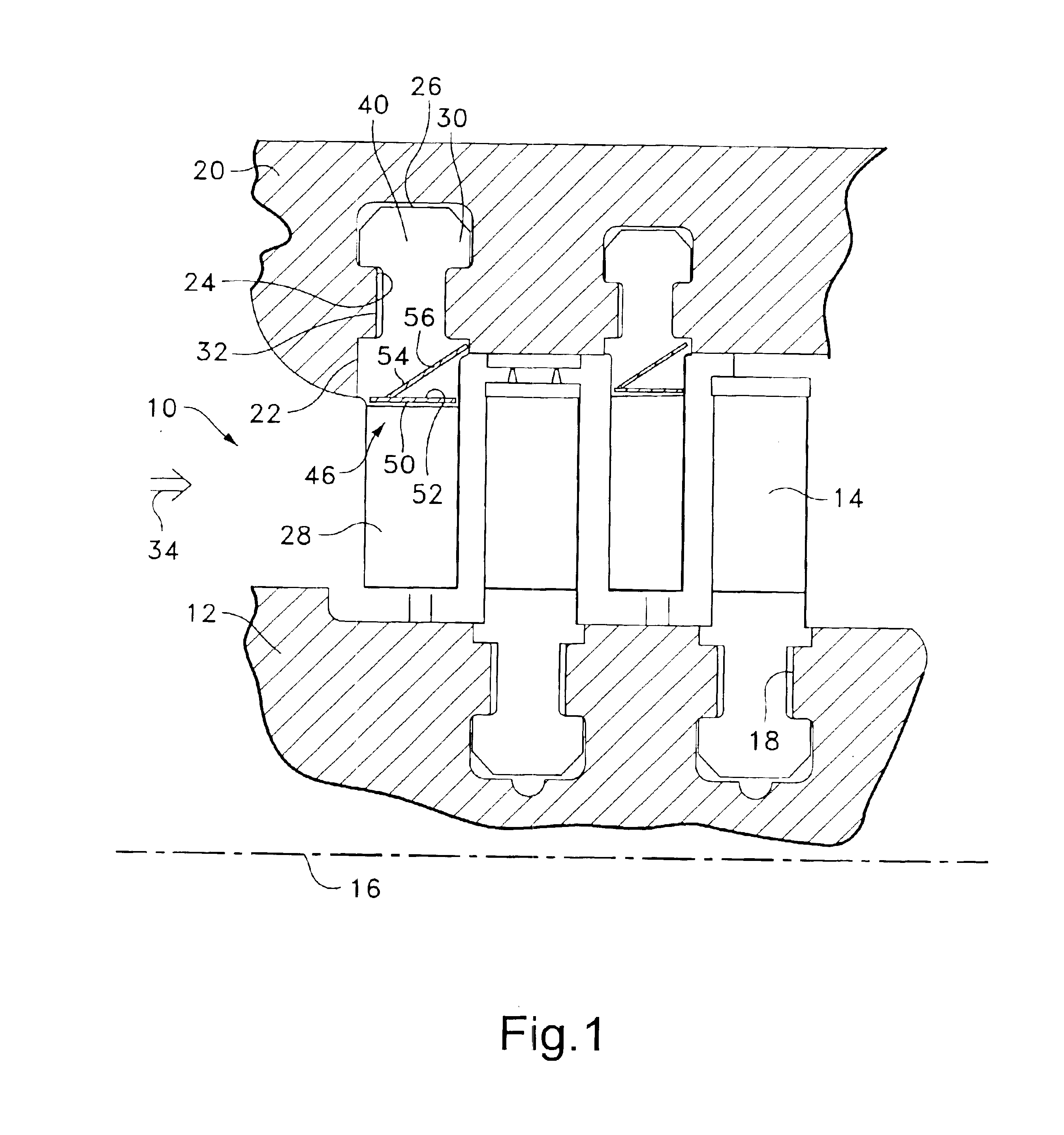
Referring now to the drawings, particularly to FIG. 1, there is illustrated a portion of a steam turbine, generally designated 10, including a rotor 12 mounting a plurality of circumferentially spaced buckets 14 about the periphery of the rotor, the rotor having an axis of rotation 16. As illustrated, the buckets are arrayed in circumferentially extending grooves 18 in the rotor as is common in constructions of this type. A steam turbine casing 20 surrounds the rotor and includes a plurality of nozzle segments 22 spaced circumferentially one from the other located in grooves 24 in casing 20. Each nozzle segment 22 includes a base 26 and at least one partition or stator vane 28 projecting radially inwardly from the base 26, adjacent vanes 28 forming nozzles. As conventional, it will be appreciated that each of the circumferential array of nozzle segments in conjunction with the following circumferential array of buckets 14 form a turbine stage, two stages being illustrated in FIG. 1....


PUM


Abstract

Nozzle segments mounting vanes are received in circumferentially extending, generally dovetail-shaped grooves in an outer casing of a steam turbine, the nozzle segments forming part of a stage with rotating buckets of the steam turbine. The inclined slashfaces of the adjoining bases of the nozzle segments are provided with circumferentially opening slots to receive spline seals. The spline seals preclude or minimize steam leakage flow past the gap between the adjoining nozzle segments thereby enhancing the steam flow through the partitions of the nozzles.

Description

BACKGROUND OF THE INVENTIONThe present invention relates generally to seals between circumferentially registering slashfaces of nozzle segments in a steam turbine and particularly relates to spline seals between the slashfaces of the nozzle segments.In steam turbines, there are static nozzles including stator vanes, i.e., airfoils, circumferentially spaced one from the other about a rotor mounting circumferentially spaced buckets. Each set of nozzles and buckets forms a turbine stage. The nozzles turn the steam flow into the buckets which, in turn, extract work from the steam flow. In steam turbines, it is critical to minimize or eliminate as many leakage paths as possible within the steam flowpath of the turbine and any secondary leakage circuits. While impulse steam turbines typically have a wheel and diaphragm construction, reaction steam turbines typically utilize a drum rotor construction. In an impulse design, the stage pressure drop is primarily taken across the stationary no...

Claims


Application Information

Patent Timeline
IPC IPC(8): F01D11/00F01D9/04F01D25/00F01D25/24F16J15/08
CPCF01D11/005
Inventor BURDGICK, STEVEN SEBASTIAN
Owner GENERAL ELECTRIC CO
Why Eureka
Try Eureka