
Lighting assembly

a technology of light assembly and light fixture, which is applied in the direction of lighting and heating equipment, fixed installation, and support devices for lighting, etc., can solve the problems of significant amount of light blocking, difficulty in ensuring the safety of viewers, and the chance of viewers encountering intense light, so as to improve the inherent disadvantages and reduce the amount of glare

Inactive Publication Date: 2005-01-18
ALLAIRE THOMAS C
View PDF6 Cites 14 Cited by
  • Summary
  • Abstract
  • Description
  • Claims
  • Application Information

AI Technical Summary

Benefits of technology

The present invention provides many of the advantages of the torchiere-type light while at the same time improving upon the inherent disadvantages of that lighting application. In particular, the light source for the present invention is contained in a housing that is recessed in a ceiling or other structure and directed toward a pendant reflector similar to the reflective bowl provided behind the lighting element in torchiere-type lights. This provides a construction for reflecting and diffusing light. Page: 3 The resulting construction results in a reduction in the amount of glare present at the light source, allows for the utilization of glass and heat-sensitive materials that cannot otherwise be used in ceiling lighting fixtures, as well as the use of the latest lamp technologies, such as fluorescent, HID, LED, and halogen light sources. In contrast to conventional pendant fixtures, the present invention provides a recessed light source with a non-electrical suspension and reflector.
Preferred embodiments of the present invention use a single, efficient focused beam lamp, rather than multiple small flood lamps. The design makes use of a hidden recessed housing for the larger lamp, as well as novel recessed housings, and allows for single lamp replacement maintenance. The passive reflector of the present invention, which does away with visible lamp and electrical hardware, provides a more pleasing, shallow profile, allows use of heat sensitive materials, with reduced fire hazard, and enables the use of less opaque, more transparent materials. Particular embodiments include a slender suspension, provided by a continuous loop to provide simpler height (drop), slope, and leveling adjustments. The suspension can be effectuated by variable lacing configurations, or fixed length chain or spoke suspension materials.
Additionally, the present invention incorporates specific ceiling structures, not present in conventional lights, such as pendant fixtures, that are designed to enhance the diffusion of the generated light. Also, because the light source is not incorporated as part of the pendant reflector, the attendant fixture and lighting elements do not obstruct movement within a room, as conventional floor lamps can. Further, the absence of such elements allows more flexibility in the choice of materials for the pendant reflector itself, due to the reduced proximity of the light source to the reflector.
An embodiment of the present invention includes a light source contained within a housing recessed within a ceiling. Illumination from the light shines downward in a substantially vertical orientation and reflects off a concave reflector suspended from the ceiling and positioned directly in the path of the light. The result is that the generated light is both shielded by the pendant reflector and diffused by being reflected onto the walls and ceiling. The suspension apparatus for the pendant reflector includes a continuous loop of flexible cord or ire that is threaded between the ceiling and the reflector. This allows the orientation of the pendant reflector to be adjusted easily without special tools. In addition, the present invention can be outfitted with a reflector dome or reflector cove positioned around the light source and opposite the reflective surface of the pendant reflector. These aspects serve to redirect the diffused light reflected by the pendant reflector while shielding a viewer from the intense light present at its point source.

Problems solved by technology

In many instances, the light intensity is great enough to cause discomfort or harm to any person viewing the light at its point source.
While all of these conventional arrangements are intended to provide diffused light with minimal light loss, it remains that a significant amount of light must be blocked in order to reduce the chance that a viewer will encounter intense light at its point source.
However, there are disadvantages to torchiere-type lights as well.
In particular, the pedestal usually must be tall, which makes the lamp inherently unstable; the intensity and heat produced by the luminaire is usually greater than that of an ordinary household light bulb, thereby posing a greater fire risk; and the wiring used by a torchiere-type light is similar to that used in ordinary table and floor lamps, which can contribute to common household accidents.
Thus, while existing lighting applications have increased the amount of useable light and improved shielding, inherent disadvantages continue to exist.

Method used


Image

  • Lighting assembly
  • Lighting assembly
  • Lighting assembly

Examples


Embodiment Construction

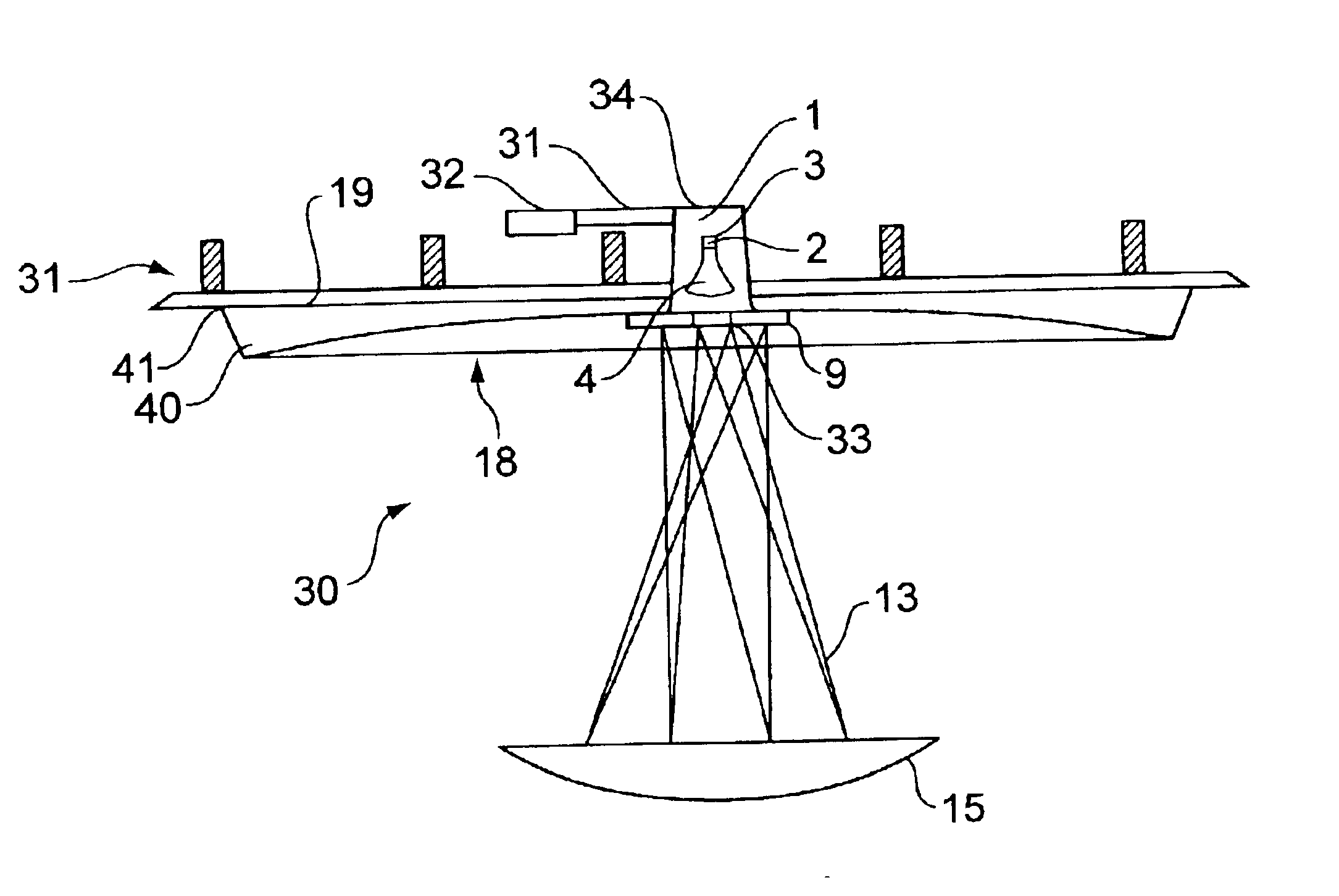
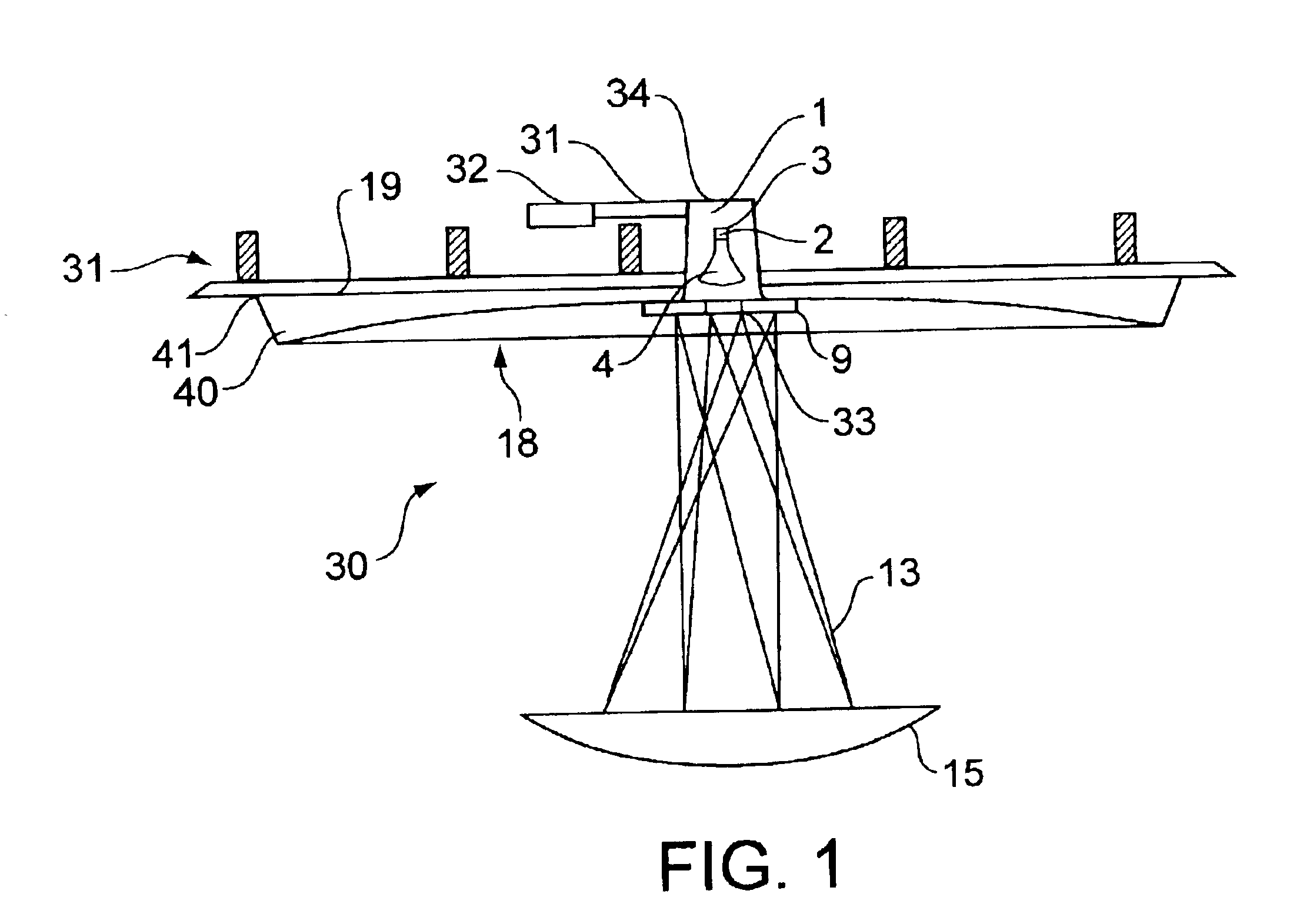
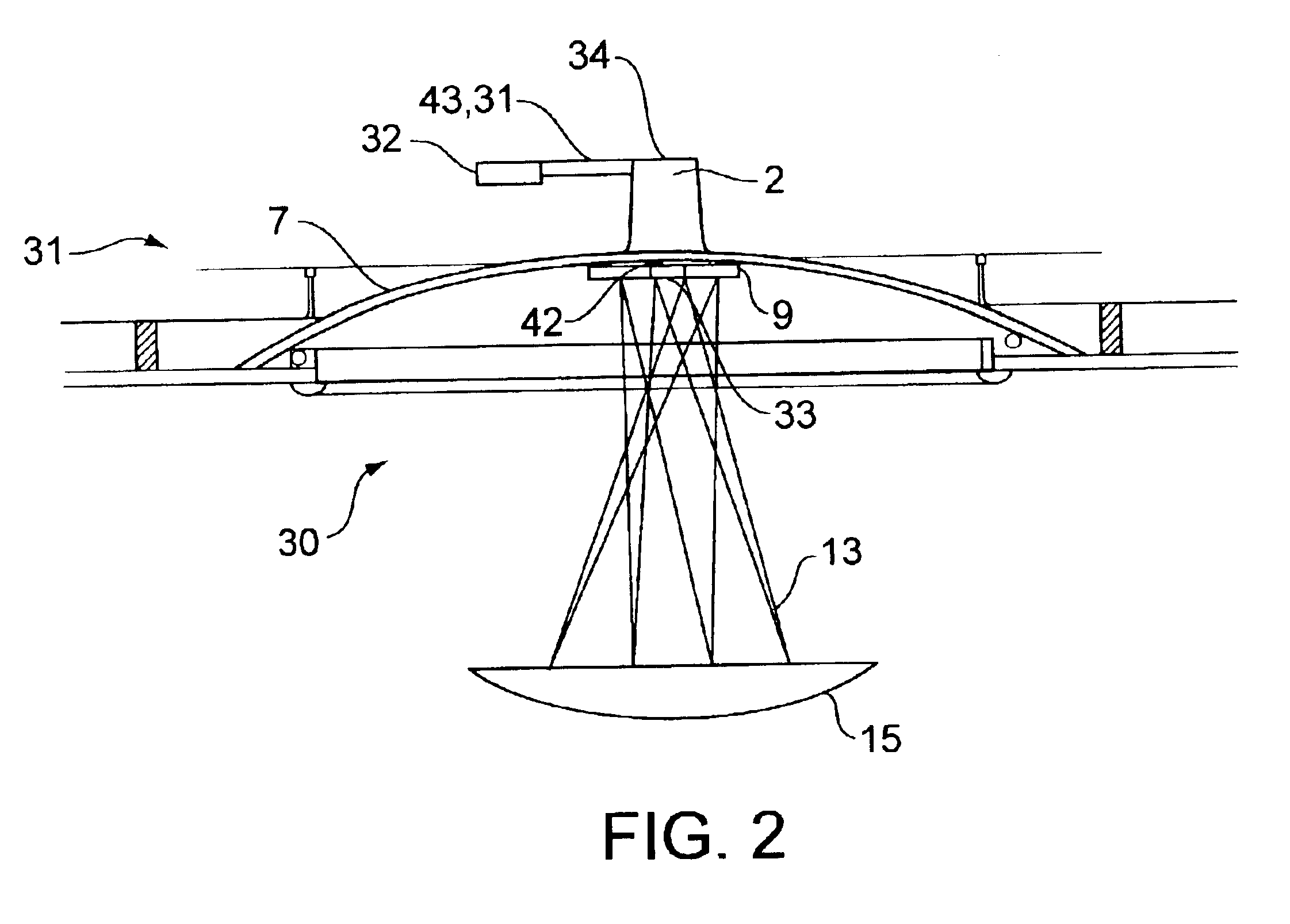
Referring to FIG. 1, a lighting apparatus 30 according to the present invention includes a luminaire 1 that is contained within a luminaire housing 2. The luminaire housing 2 is fitted to a ceiling 31 such that it is recessed within the ceiling 31. The luminaire housing 2 is attached to the ceiling 31 using common construction techniques, and power is provided to the luminaire 1 by conventional means, such as a direct connection by wiring 43 to a junction box 32 or other power source. A standard-type light socket 3 is fitted to the interior base of the luminaire housing 2 such that the bulb 4 portion of the luminaire 1 is directed toward the open end 33 of the luminaire housing 2, that is, downward from the ceiling 31. It is contemplated that the luminaire housing 2 of the present invention can accommodate any type of residential or commercial light socket or connection, such as a receptacle for a halogen bulb or compact fluorescent lamp, or wires and clips for two-terminal style su...


PUM


Abstract

A lighting assembly includes a light socket, a first reflector base, and a second reflector base. The light socket is at least partially disposed in a housing, and is used to secure and provide electrical power to a light source. The first reflector base has an aperture through which the light socket is accessible, and a reflective surface generally facing away from the light socket, and therefore the light source. The second reflector base is connected to the first reflector base, the light source housing, or both, and has a reflective surface generally facing the light source and the reflective surface of the first reflector base. Light provided by the light source is reflected from the second reflective surface and then the first reflective surface, providing indirect lighting for an observer.

Description

FIELD OF THE INVENTIONThe present invention relates to lights, light fixtures, and other lighting apparatus for residential and commercial use.BACKGROUND OF THE INVENTIONIn the field of residential and commercial lighting, a variety of applications generate light from point sources. Whether a lighting application utilizes charged gas particles, such as a neon tube, or a current resisting filament, such as an ordinary household light bulb, the intensity of the light generated at the point source can be significant. In many instances, the light intensity is great enough to cause discomfort or harm to any person viewing the light at its point source. As a result, numerous constructions have been utilized to shield viewers from the intense light emanating from the point where the light is generated. At the same time, these designs have been intended to facilitate the diffusion of as much of the generated light as possible in order to maintain an efficient lighting application. The resul...

Claims


Application Information

Patent Timeline
IPC IPC(8): F21V7/00F21S6/00F21S8/02F21S8/04F21S8/06F21V17/06F21V17/16F21V21/008
CPCF21S6/003F21S6/005F21S8/02F21V7/0025F21V17/102F21V7/0008F21V17/164
Inventor ALLAIRE, THOMAS C.
Owner ALLAIRE THOMAS C
Learn More