
Splicing joint and method for synchronous drive belt

Inactive Publication Date: 2005-01-18
CONTITECH USA INC
View PDF3 Cites 13 Cited by
  • Summary
  • Abstract
  • Description
  • Claims
  • Application Information

AI Technical Summary

Benefits of technology

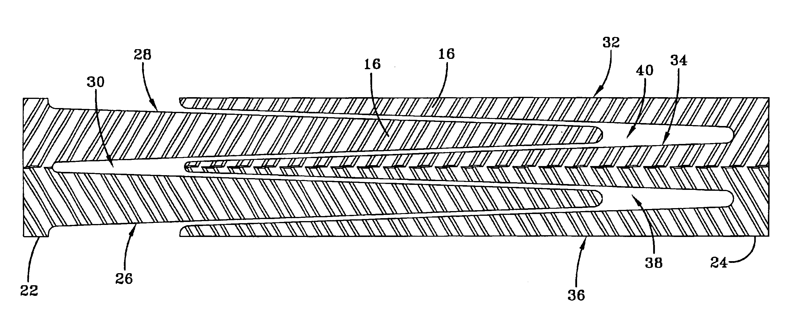
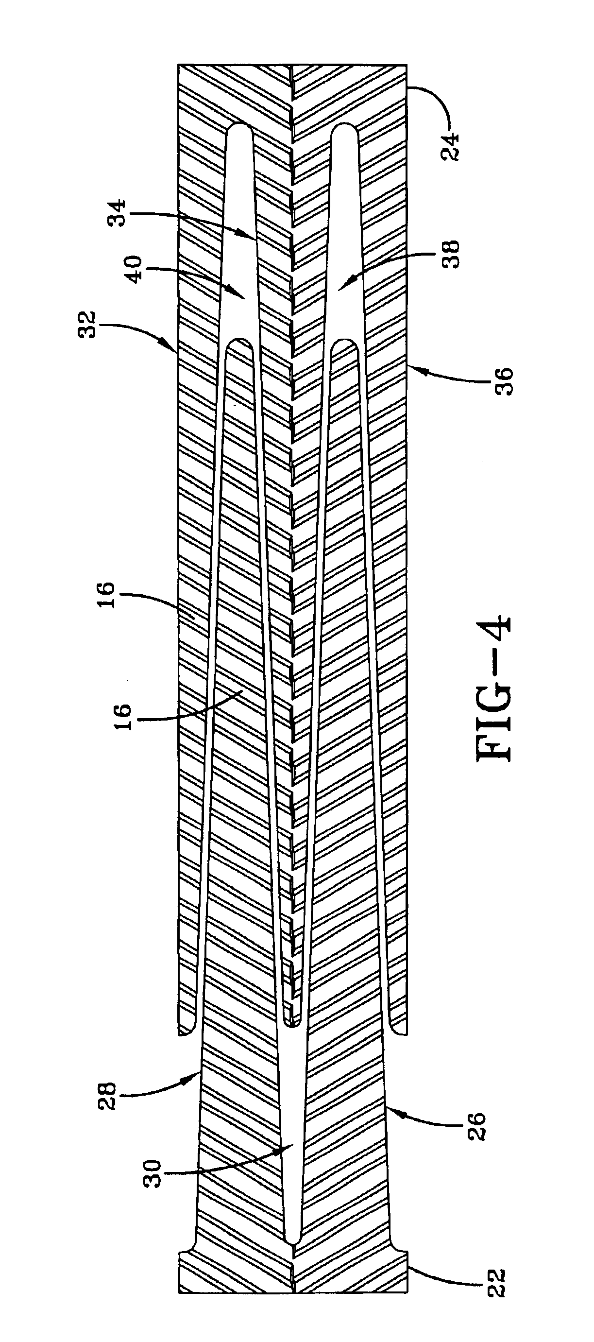
In accordance with the practice of the present invention there is provided a splice joint for joining first and second synchronous drive belt ends. The drive belt is of a type comprising a reinforcement material layer covering a base layer formed from a first thermoplastic material. The joint comprises a fused portion of the base layer of the first and second belt ends that define a splice region and at least one coating layer of thermoplastic material overlapping the reinforcement layer of the end portions in the splice region. The coating layer is comprised of a second elastomeric material intended to melt and penetrate into interstices of the reinforcement material layer while within the mold press. Migration of the base layer material through the reinforcement material layer to the pulley-engaging surface is thereby inhibited.
In accordance with another aspect of the invention, the coating layer is composed of polyethylene having low friction and high wear resistance. Another aspect of the invention is to provide at least a second coating layer wherein the first coating layer may be comprised of low density polyethylene and the outer, secondary layer, high density poly

Problems solved by technology

While the aforementioned splice and splicing method works well and results in a belt having the desired shape and functional strength at the splice joint, several undesirable consequences are unavoidable from the practice of this state of the art methodology.
First, during the fusion procedure, the molten thermoplastic belt base layer material tends to penetrate into and through the interstices of the fabric reinforcement layer.
When cooled, any such material present on the outer fabric surface of the belt at the splice represents an irregularity that, when contacting a mating pulley surface, can cause an undesired squeaking or chirping noise.
This noise may be severe and can be misinterpreted as a functional defect in the belt.
Secondly, the coefficient of friction of the belt base thermoplastic material present on the outer surface of the belt at the splice joint is generally higher than desired and the material is not sufficiently wear resistant.
The splice joint may consequently be susceptible to a higher than desired rate of wear at the joint.

Method used


Image

  • Splicing joint and method for synchronous drive belt
  • Splicing joint and method for synchronous drive belt
  • Splicing joint and method for synchronous drive belt

Examples


Embodiment Construction

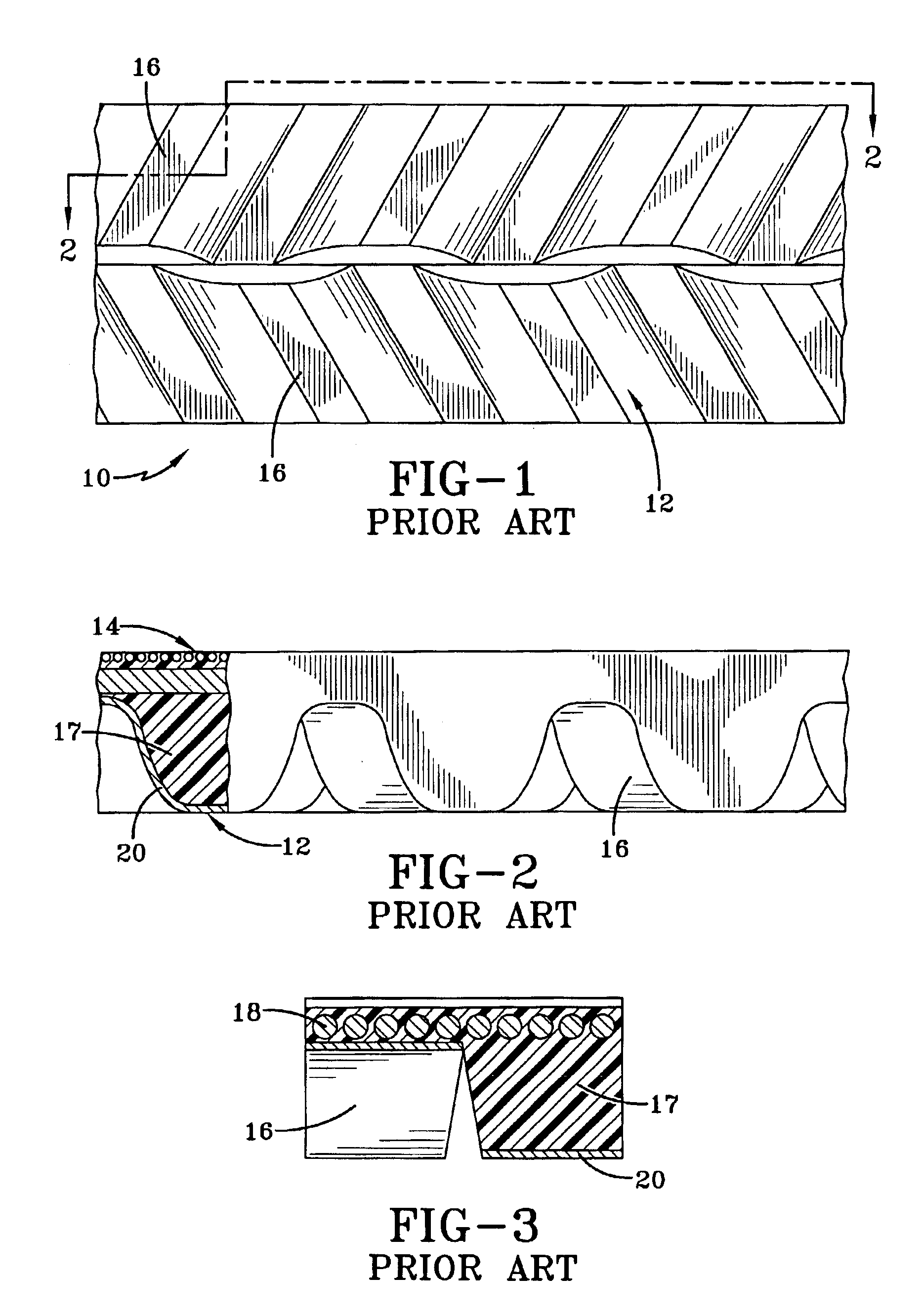
The drawings illustrate a synchronous drive belt 10 of a type in use in conventional drive systems such as in automotive transmission applications. A belt 10 such as shown in FIGS. 1-3 includes a toothed surface 12 and a planar opposite untoothed surface 14. Spaced apart along the surface 12 are a series of drive teeth 16. The belt is made of a resilient elastomer base layer 17 typically formed of a plastic resin such as polyurethane. The belt 10 is also typically reinforced with a longitudinal tensile member 19 made up of a plurality of cords 18 of a high elastic modulus. Such cords may be made from glass fiber, carbon fiber, steel, polyester, high tenacity rayon or, preferably, steel. Such a belt is disclosed in U.S. Pat. No. 5,209,705, incorporated by reference herein.

The tooth surface 12 or the belt 10 may be reinforced with a layer 20 of abrasion resistant fabric such as nylon. The fabric includes interstices (not shown) between woven fibers that extend through the fabric from ...


PUM

PropertyMeasurementUnit
Elastomericaaaaaaaaaa
Densityaaaaaaaaaa
Frictionaaaaaaaaaa

Abstract

A splice joint is for joining first and second synchronous drive belt ends, of the belt type comprising a reinforcement material layer covering a base layer formed from a first thermoplastic material. The joint comprises a fused portion of the base layer of the first and second belt ends that define a splice region. At least one coating layer of thermoplastic material overlaps the reinforcement layer of the end portions in the splice region. The coating layer is comprised of a second elastomeric material intended to melt and penetrate into interstices of the reinforcement material layer while within the mold press. Migration of the base layer material through the reinforcement material layer to the pulley-engaging outer surface is thereby inhibited. The second elastomeric material composing the coating layer may be selected to provide desired frictional and wear characteristics.

Description

FIELD OF THE INVENTIONThe present invention relates generally to a synchronous drive belt and specifically to a splicing joint and method for connecting opposite ends of a drive belt together to form an uninterrupted loop.BACKGROUND OF THE INVENTIONConventional synchronous drive belts are known in the industry and find utility in sundry applications. Such belts include a resilient elastomeric base layer reinforced with longitudinal tensile members. The belt base layer is typically formed of a suitably strong yet pliable material such as polyurethane. A series of teeth are formed along the base layer to sequentially engage corresponding pulley cavities. The tooth surface may be reinforced, if required, with an abrasion resistant fabric such as nylon. U.S. Pat. Nos. 4,679,459; 4,951,261; 5,209,705; and 5,421,789 are representative of the state of the art in synchronous drive belt structures.Synchronous belting made from thermoplastic elastomer is often made in open ended long continuo...

Claims


Application Information

Patent Timeline
IPC IPC(8): F16G3/00F16G3/10
CPCF16G3/00F16G3/003B29C66/72141B29C66/8167F16G3/10B29C65/18B29C65/4815B29C65/5042B29C66/1142B29C66/223B29C66/30326B29C66/4322B29C66/4324B29C66/723B29C66/729B29C66/73921B29C66/81435B29C66/832B29L2016/00B29L2031/7094B29C65/5021B29L2031/7092B29C66/71B29C66/7212B29K2021/003B29C66/81419B29C66/81425B29C66/81431B29K2075/00B29K2305/00B29K2023/16B29K2023/065B29K2023/0633B29K2023/06
Inventor GREGG, MICHAEL JOHN WILLIAMNGUYEN, HONG XUAN
Owner CONTITECH USA INC
Learn More