Method of metallurgically bonding articles and article therefor

a technology of metallurgy bonding and articles, applied in the direction of roofs, superstructure connections, solid-state devices, etc., can solve the problems of accelerated electrode wear, difficult resistance welding, and entrapped vapors introducing contaminants and/or voids within solidified weld nuggets

Inactive Publication Date: 2005-01-18
GM GLOBAL TECH OPERATIONS LLC +1
View PDF13 Cites 21 Cited by
  • Summary
  • Abstract
  • Description
  • Claims
  • Application Information

AI Technical Summary

Benefits of technology

The invention is about a special surface design for laser-welded metallurgical bonding. The surface has multiple channels that are about 1 to 1000 microns deep. When the two parts are pressed together and heated with a laser, the channels help to melt the surface and create a strong bond. The channels are arranged in a pattern along the surface where the laser moves. The design makes it easier to create strong bonds with laser welding.

Problems solved by technology

The patent text discusses the challenges faced by welders when bonding metallurgical materials, such as galvanized and aluminum parts, due to the release of vapors and the thickness of the parts being bonded. The technical problem addressed by the patent is to provide a method and arrangement that overcomes these drawbacks and improves the metallurgical bond.

Method used


Image

  • Method of metallurgically bonding articles and article therefor
  • Method of metallurgically bonding articles and article therefor
  • Method of metallurgically bonding articles and article therefor

Examples


Embodiment Construction

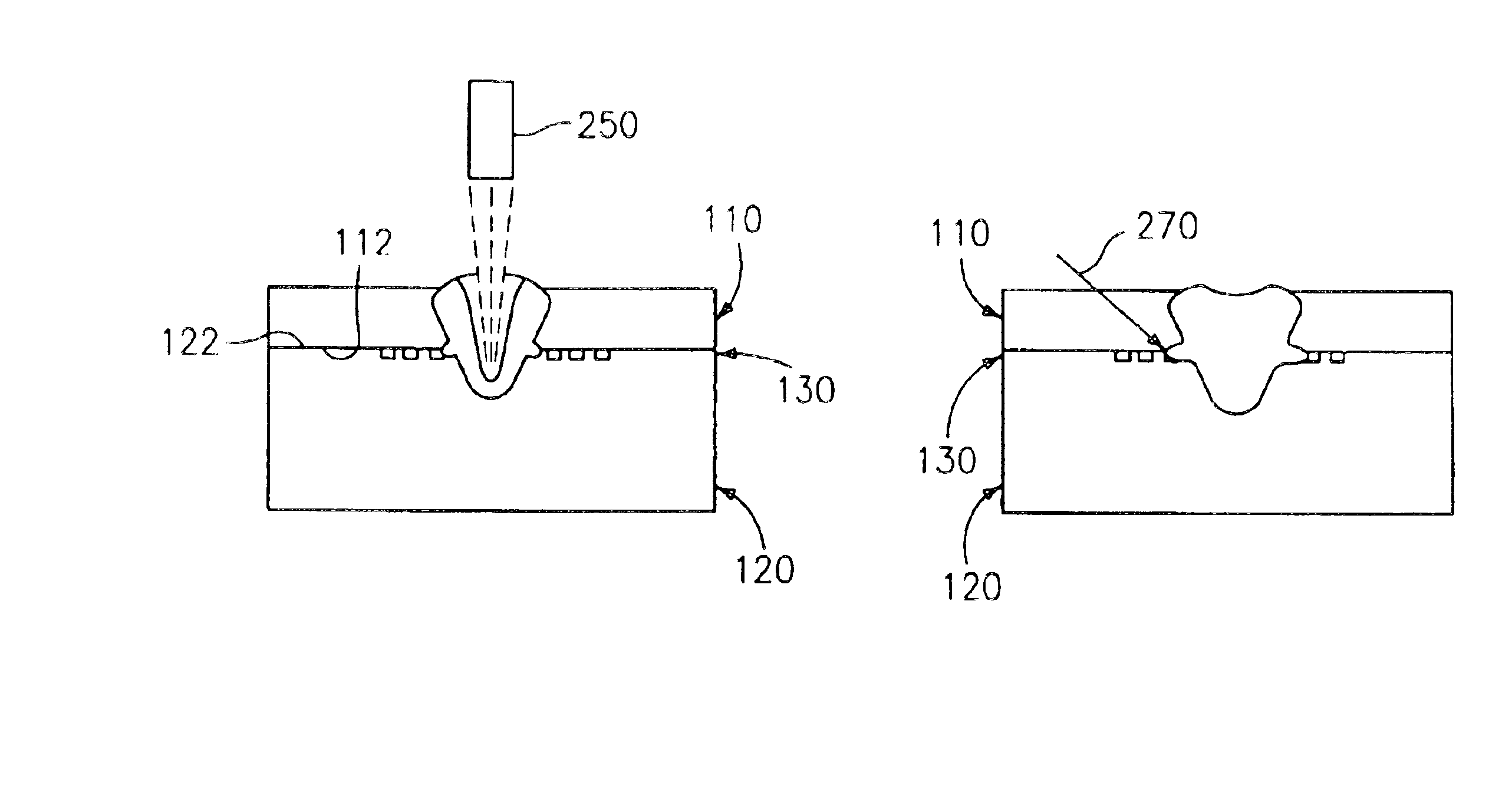
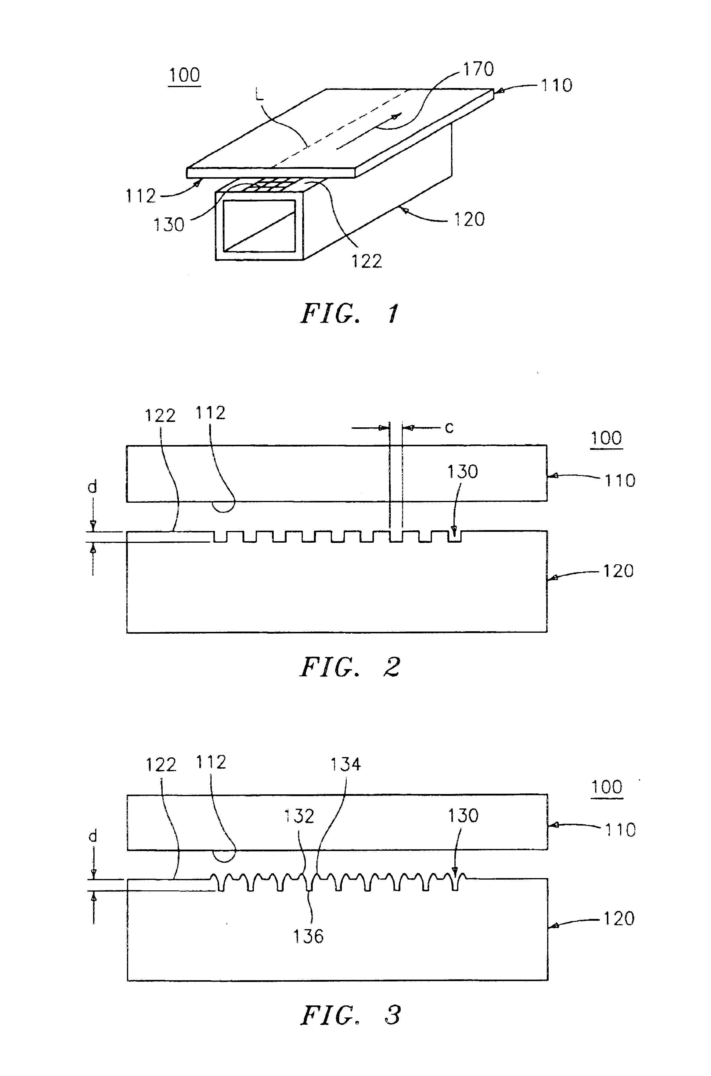
Embodiments of the invention provide an article having a first part and a second part that is suitable for metallurgical bonding, and a method for metallurgically bonding the article. In particular, the first part may be a door panel of an automobile and the second part may be a support structure of the automobile to which the door panel is bonded. The first part may be made from coated metal, such as galvanized steel for example, and the second part may be made from steel, aluminum, or any other material suitable for metallurgical bonding. The second part may also be made using a hydroforming process. The metallurgical bond may be accomplished using resistance welding, arc welding, laser welding, or any other process suitable for producing a metallurgical bond at a faying surface, such as electron beam welding or hybrid laser welding for example. As used herein, the term faying surface refers to the bonded region where a first surface of the first part interfaces with a second surf...


PUM

PropertyMeasurementUnit
Lengthaaaaaaaaaa
Lengthaaaaaaaaaa
Lengthaaaaaaaaaa

Abstract

An article suitable for laser-welded metallurgical bonding, the article having a first part having a lower surface, and a second part having an upper surface is disclosed. The lower surface of the first part is disposed at the upper surface of the second part to provide for a faying surface thereat. The faying surface has a plurality of channels with a depth equal to or greater than about 1 micron and equal to or less than about 1000 microns. The article is suitable for laser-welded metallurgical bonding at the faying surface. The plurality of channels has a repetitive pattern of channels arranged along a path of the faying surface in a direction of the metallurgical bonding action.

Description


Claims


Application Information

Patent Timeline
Owner GM GLOBAL TECH OPERATIONS LLC
Why Eureka
Try Eureka