Multiple beam linear accelerator system

Active Publication Date: 2005-01-18
MEVEX CORP
View PDF3 Cites 55 Cited by
  • Summary
  • Abstract
  • Description
  • Claims
  • Application Information

AI Technical Summary

Benefits of technology

It is an object of the present invention to obviate or mitigate at least one disadvantage of previous multiple beam linear accelerator systems. It is a particular object of the present invention to provide a multiple beam linear accelerator

Problems solved by technology

The klystrons and HV supplies are particularly expensiv

Method used


Image

  • Multiple beam linear accelerator system
  • Multiple beam linear accelerator system
  • Multiple beam linear accelerator system

Examples


Embodiment Construction

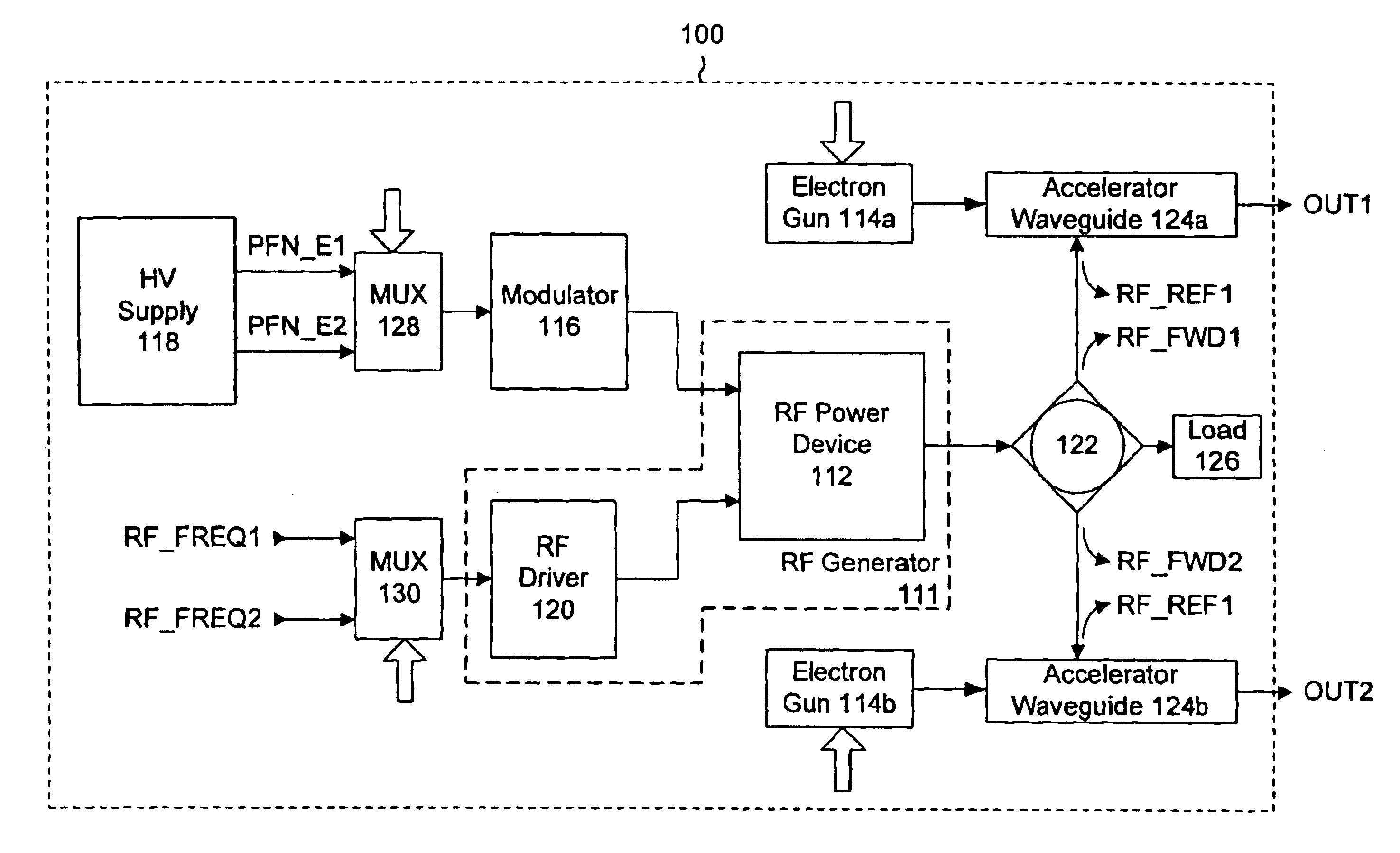
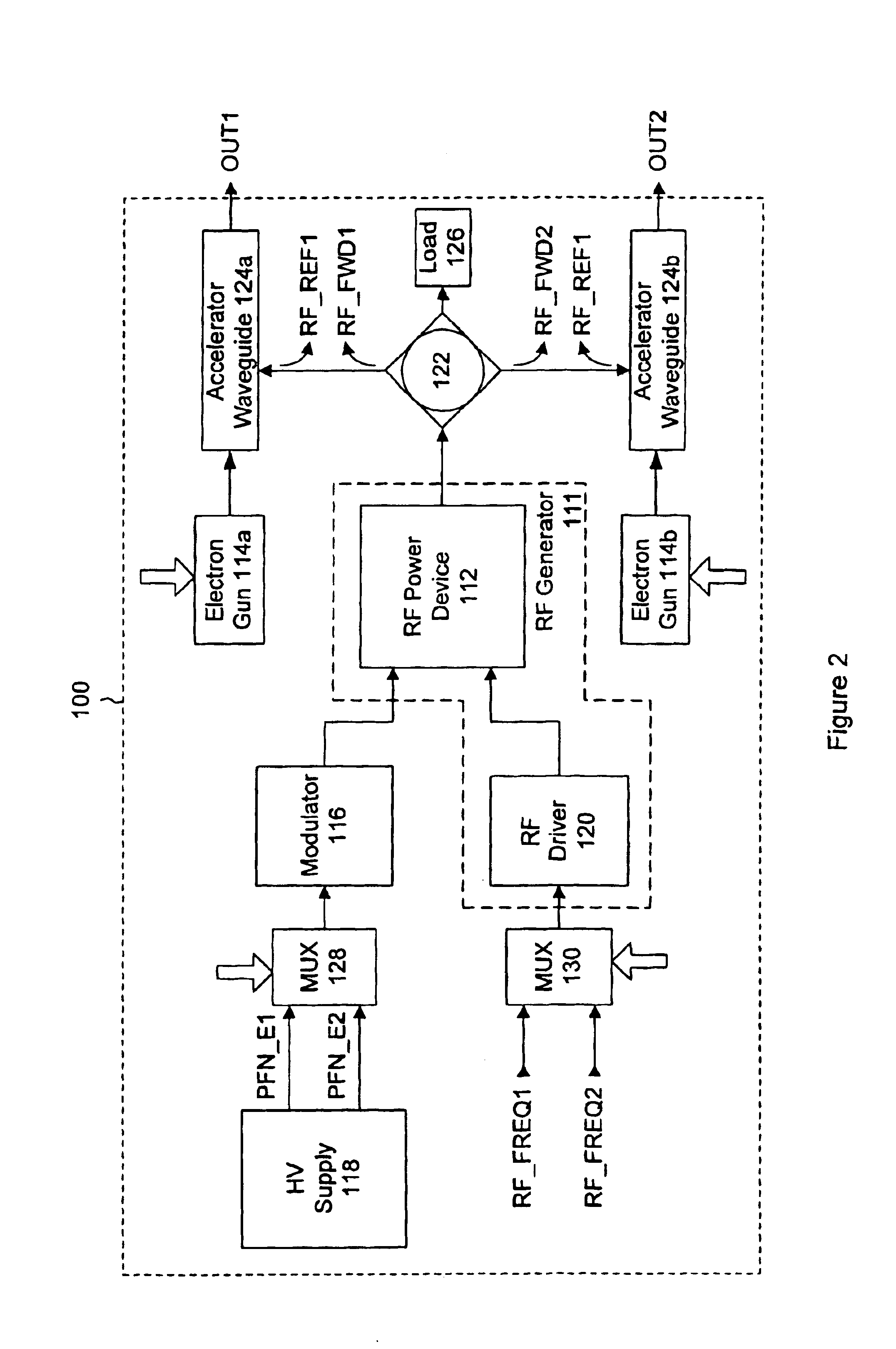
Generally, the present invention provides a multiple beam linear accelerator system where two or more accelerator waveguides are driven by a single high power microwave device. The present invention relies upon a multiplexed RF power system for driving the plurality of accelerator waveguides. Each accelerator waveguide is addressed at a different RF frequency, and the high power microwave device generates pulses at the appropriate RF frequency and power for each accelerator waveguide.

Referring to FIG. 2, a block diagram of a linear accelerator according to an embodiment of the present invention, and generally indicated at reference numeral 100, is shown. System 100 illustrates a dual-beam linear accelerator system having two linear accelerator waveguides 124a and 124b. As will be apparent to those of skill in the art, the present invention can be applied to systems having two or more accelerator waveguides. Generally, the invention requires resonant accelerator waveguides to functio...


PUM


Abstract

A multiple beam linear accelerator system and method where two or more accelerator waveguides are driven by a single high power microwave source. A single RF power system is multiplexed to drive the plurality of accelerator waveguides. Each accelerator waveguide is addressed at a different RF frequency, and the microwave source generates pulses at the appropriate RF frequency for each accelerator waveguide on a pulse-by-pulse basis.

Description

FIELD OF THE INVENTIONThe present invention relates generally to linear accelerators. More particularly, the present invention relates to multiple beam linear accelerator systems and their control.BACKGROUND OF THE INVENTIONA linear accelerator, or linac, is a device used to accelerate electrons to high velocities. For most applications involving particle energies of greater than 1 MeV, radio frequency linear accelerators, or RF linear accelerators, are used. RF linear accelerators have many medical and industrial applications, including radiation therapy, medical and food product irradiation, polymer cross-linking, pest control, ion implantation in semiconductor production, and non-destructive testing.A block diagram of a simplified RF linear accelerator system is shown in FIG. 1. The linear accelerator system 10 generally consists of an RF generator 11 to generate high power microwave pulses that set up electric fields in a linear accelerator waveguide 24, which are then used to a...

Claims


Application Information

Patent Timeline
IPC IPC(8): H01J23/00H05H7/02
CPCH05H7/02
Inventor BROWN, DAVID A.HEPWORTH, DAVID J.
Owner MEVEX CORP
Why Eureka
Try Eureka