Rotational speed detector having elongate detecting surface and method of manufacturing the same

a technology of rotating speed and detecting surface, which is applied in the direction of fluid pressure measurement, instruments, mechanical equipment, etc., can solve the problems of difficult to thin resin layers, achieve accurate signals, improve rotational speed, and large air gap

Inactive Publication Date: 2005-01-18
DENSO CORP
View PDF18 Cites 19 Cited by
  • Summary
  • Abstract
  • Description
  • Claims
  • Application Information

AI Technical Summary

Benefits of technology

The present invention has been made in view of the above-mentioned problem, and an object of the present invention is to provide an improved rot

Problems solved by technology

However, it is difficult to make the resin layer thin because a certain thickness of the resin layer is neces

Method used


Image

  • Rotational speed detector having elongate detecting surface and method of manufacturing the same
  • Rotational speed detector having elongate detecting surface and method of manufacturing the same
  • Rotational speed detector having elongate detecting surface and method of manufacturing the same

Examples


Embodiment Construction

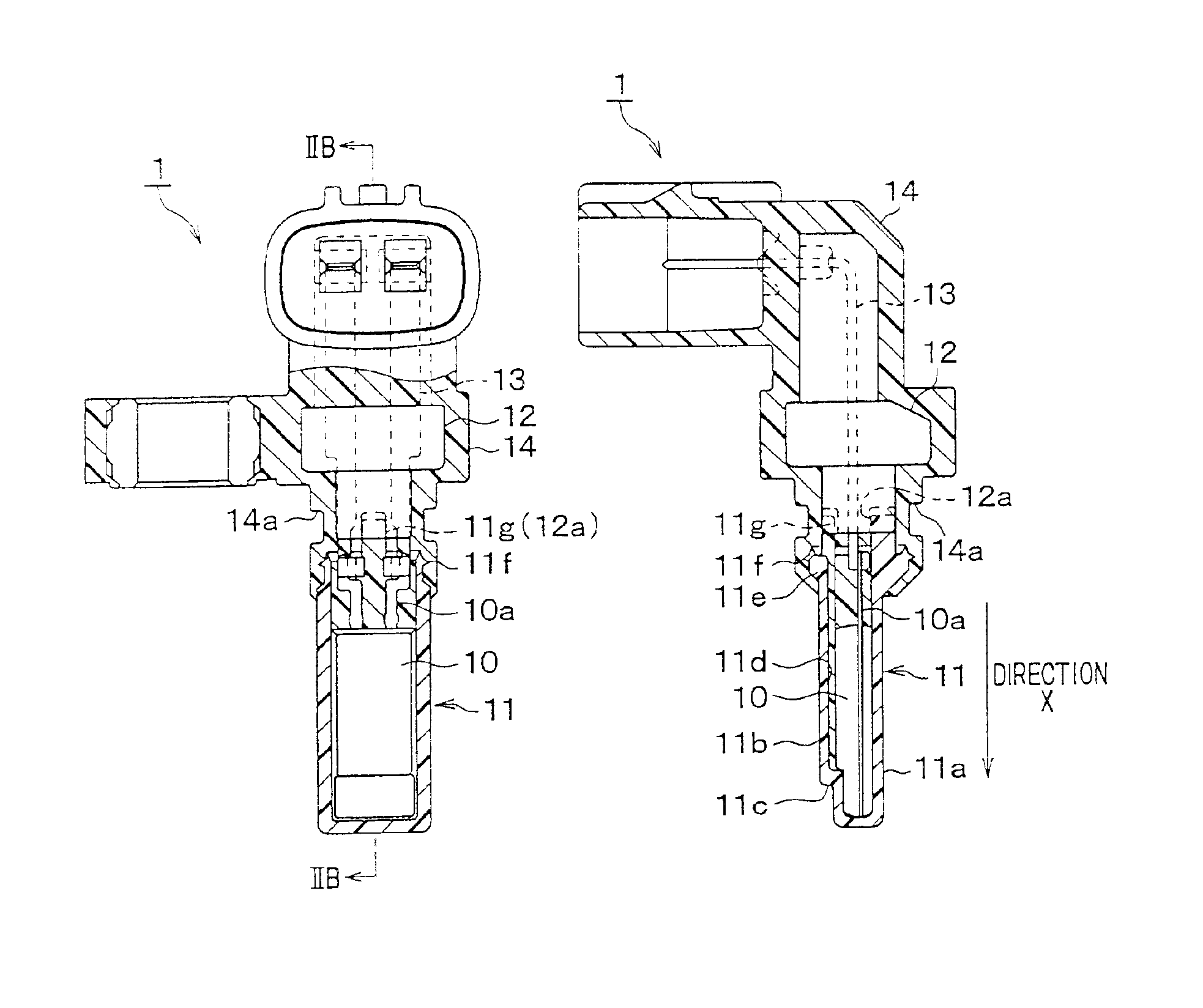
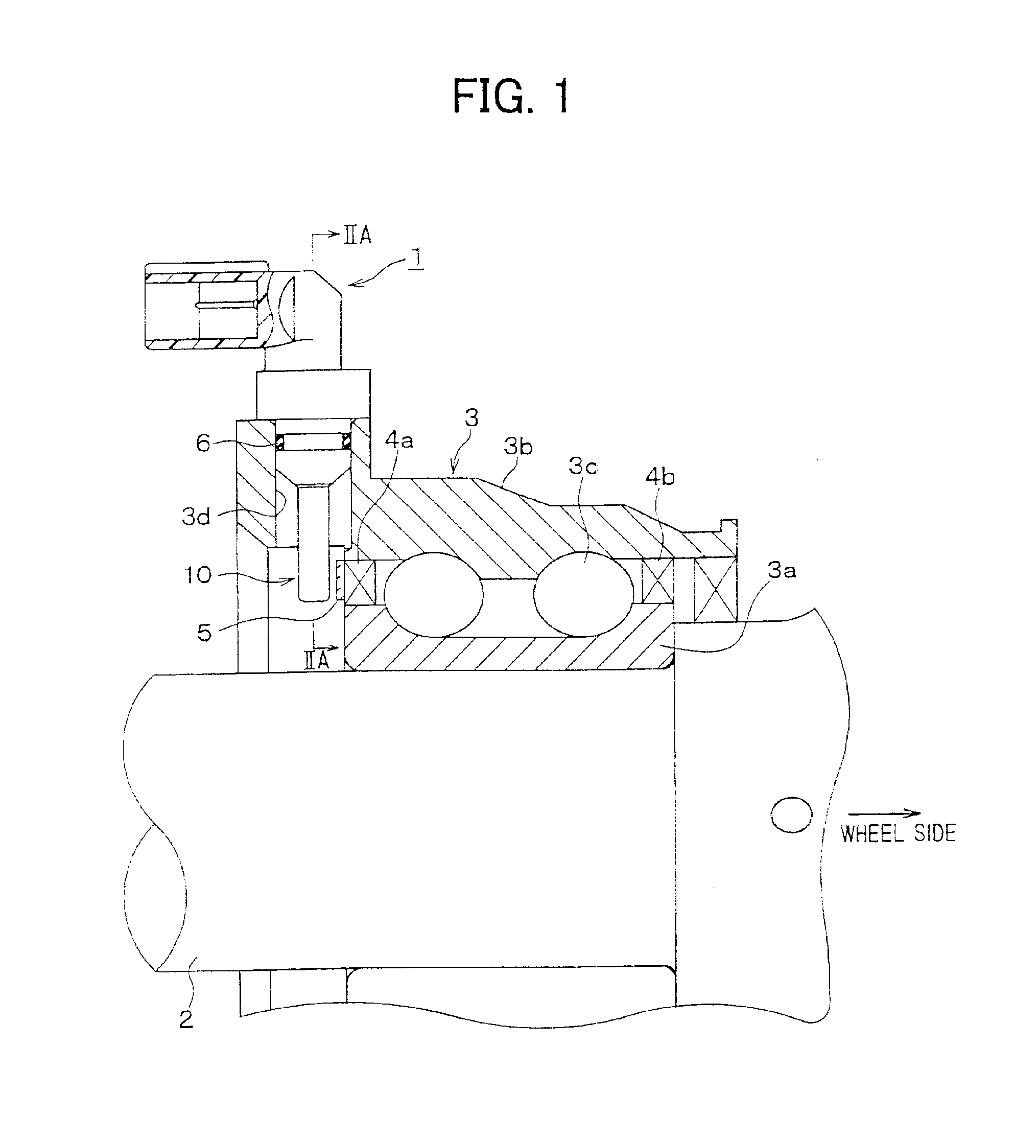
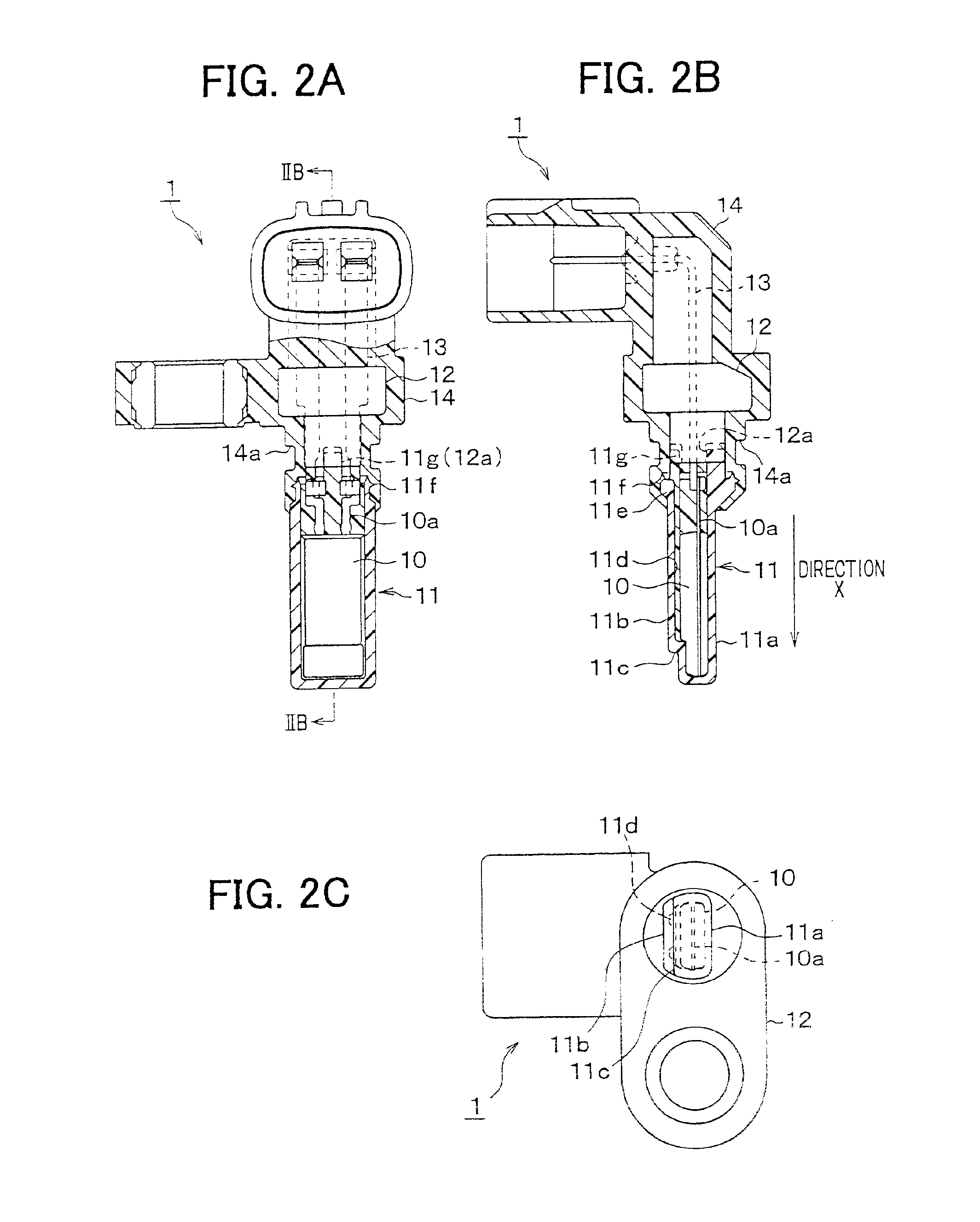
A preferred embodiment of the present invention will be described with reference to accompanying drawings. First, referring to FIG. 1, a portion of a driving axle where a wheel speed sensor 1 of the present invention is mounted will be described. A bearing 3 is disposed on a driving axle 2 of an automobile. The bearing 3 is composed of an inner ring 3a fixed to the axle 2, an outer ring 3b fixed to a vehicle body (not shown) and balls 3c disposed between the inner ring 3a and the outer ring 3b. A pair of oil seals 4a and 4b are disposed at both ends of the bearing 3, so that lubricant filling a space between the inner ring 3a and the outer ring 3b is prevented from flowing out. A ring-shaped rotor 5 is attached to one of the oil seals 4a. The rotor 5 rotates together with the inner ring 3a, representing a rotational speed of the vehicle wheel. The ring-shaped rotor 5 is magnetized to form alternately N and S poles thereon and disposed coaxially with the driving axle 2 around a circu...


PUM


Abstract

A rotational speed detector such as a wheel speed detector has an elongate housing containing a detector unit therein. The detector unit is a molded unit having a sensor element and an integrated circuit chip for processing sensor signals. A front wall of the elongate housing faces a magnetized rotor rotated by a rotating object so that the rotational speed of the rotor is detected by the detector unit. After the housing and a center rod having a terminal wire for leading out the detected electrical signals are connected to each other, a resin mold covering an outside of the center rod and a part of the housing is formed to formulate a unitary body of the rotational speed detector.

Description

CROSS-REFERENCE TO RELATED APPLICATIONThis application is based upon and claims benefit of priority of Japanese Patent Application No. 2001-199127 filed on Jun. 29, 2001, the content of which is incorporated herein by reference.BACKGROUND OF THE INVENTION1. Field of the InventionThe present invention relates to a rotational speed detector for detecting a rotational speed such as a wheel speed of an automobile and to a method of manufacturing the detector.2. Description of Related ArtAn example of a conventional wheel speed detector which is installed on a vehicle to face a rotor rotating together with a vehicle wheel is disclosed in JP-A-11-14644. In this detector, a sensor element is disposed in a depressed portion of a sensor housing, and the sensor element and associated circuits are covered with a resin material to protect them against water. The sensor element covered with the resin is positioned to face the rotor. A sufficient air gap between the detector and the rotor is requ...

Claims


Application Information

Patent Timeline
IPC IPC(8): G01P1/02G01P1/00G01P3/44G01P3/42G01P3/488G01D5/245
CPCG01P1/026G01P3/443F16C41/007
Inventor TSUGE, HIROYUKITANABE, MIKIO
Owner DENSO CORP
Why Eureka
Try Eureka