
Systems and methods for locating a ground fault without de-energizing the circuit

a technology of ground fault and circuit, applied in the field of systems and methods for locating ground faults, can solve the problems of inability to identify on which branch circuit the ground is located, inability to locate the actual source of ground, and traditional ground locating equipment falling short in detecting high resistance ground

Inactive Publication Date: 2005-01-18
WMW GROUP
View PDF2 Cites 9 Cited by
  • Summary
  • Abstract
  • Description
  • Claims
  • Application Information

AI Technical Summary

Benefits of technology

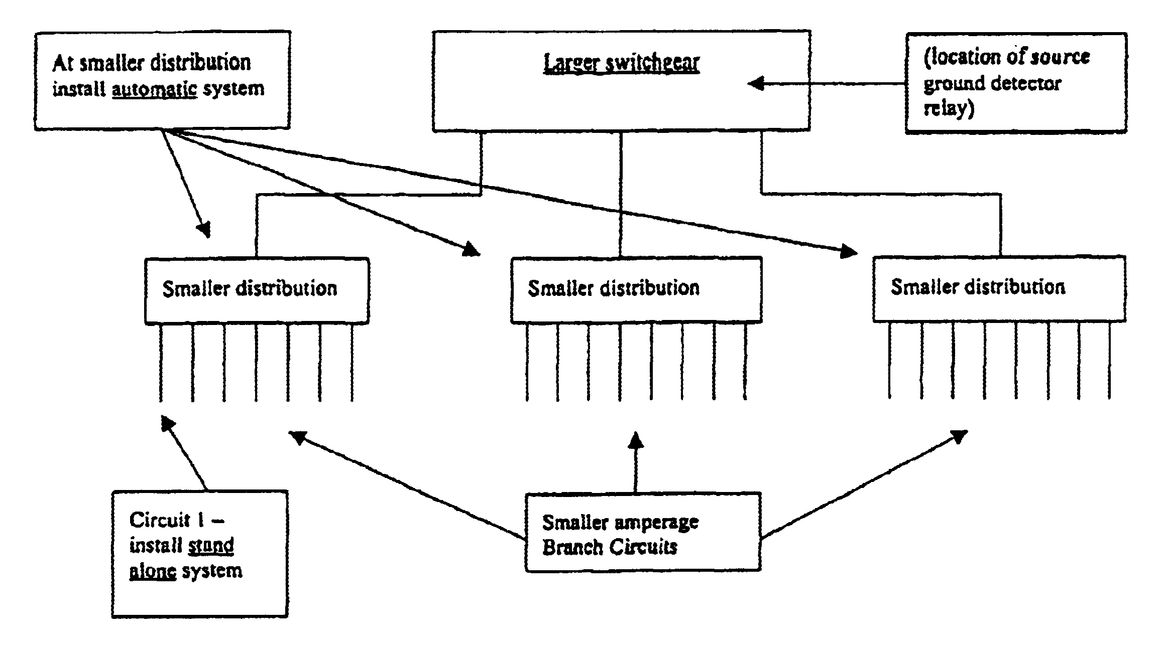
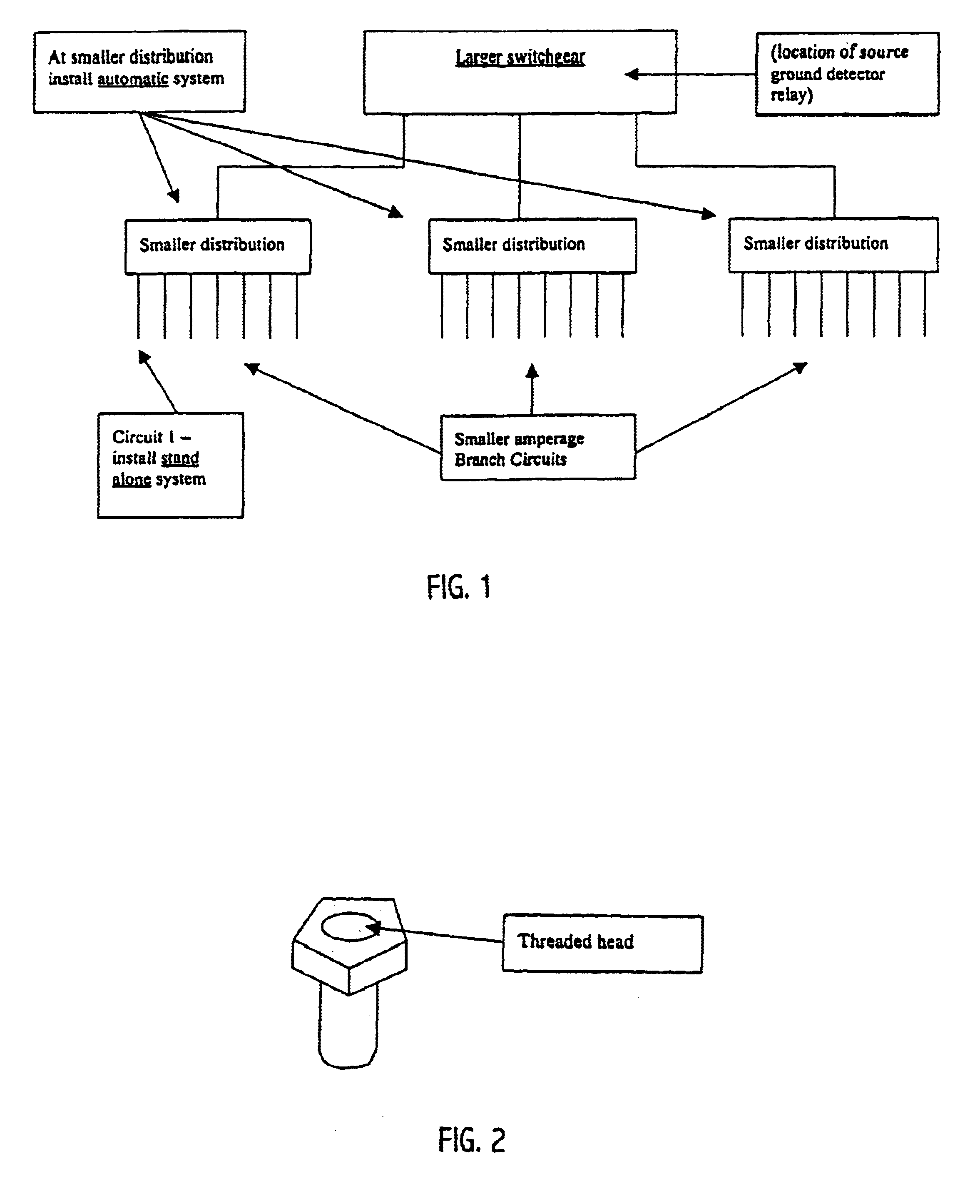
Furthermore, implementation of the present invention recognizes that grounds generally come in on lower amperage circuits, and that these circuits are generally not on the main switchgear but instead are located in a smaller distribution switchgear that is fed from the larger switchgear.
Accordingly, the systems and methods of the present invention locate any grounded circuit on an ungrounded AC or DC system without de-energizing the circuit. Once the grounded circuit is located, further troubleshooting can be performed to isolate the grounded component. These and other features and advantages of the present invention will be set forth or will become more fully apparent in the description that follows and in the appended claims. The features and advantages may be realized and obtained by means of the instruments and combinations particularly pointed out in the appended claims. Furthermore, the features and advantages of the invention may be learned by the practice of the invention or will be obvious from the description, as set forth hereinafter.

Problems solved by technology

While such a technique will alert a user that a ground is somewhere on the system, it cannot identify on which branch circuit the ground is located.
Moreover, the technique is unable to locate the actual source of the ground.
However, the portable ground locating techniques used on uninterruptible systems supplying vital loads attempt to locate the grounded circuit by varying the ground current and looking for the oscillating current on each branch circuit using a current transformer.
Accordingly, traditional ground locating equipment falls short in detecting high resistance grounds due to excessive noise on the system.
Thus, while techniques currently exist that are used to perform ground location, challenges still exist, such as poor signal to noise ratio with convention equipment.

Method used


Image

  • Systems and methods for locating a ground fault without de-energizing the circuit
  • Systems and methods for locating a ground fault without de-energizing the circuit
  • Systems and methods for locating a ground fault without de-energizing the circuit

Examples


Embodiment Construction

The present invention relates to systems and methods for locating a ground fault. More particularly, the present invention relates to systems and methods for locating any grounded circuit on an ungrounded AC or DC system without de-energizing the circuit, and enabling isolation of the grounded component of the circuit.

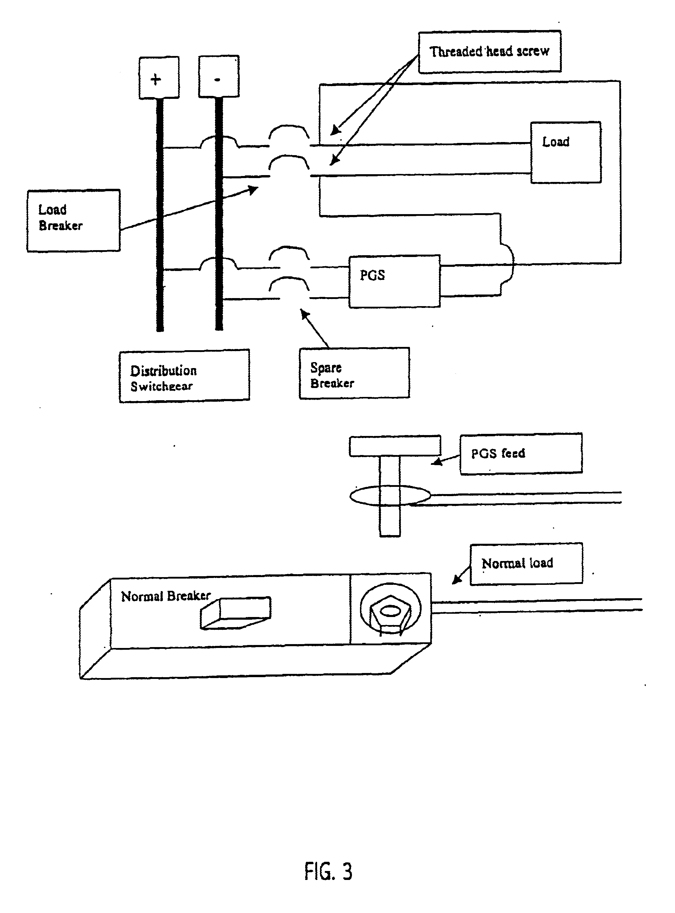
Some embodiments of the present invention enable a load to be fed through an isolation device, such as a transformer or distribution switchgear for AC systems or a DC-to-DC converter for DC systems, and isolated from the normal distribution system without ever being de-energized. Once the isolating device is paralleled with the normal source for the load, the normal source is removed, leaving the load energized and fed through the isolating device solely. Thus, any ground that comes in on the secondary side of the isolation device is isolated from the system feeding it.

Some embodiments further embrace adding a ground detector relay at the secondary side of the isolatio...


PUM


Abstract

Systems and methods for locating any grounded circuit on an ungrounded AC or DC system without de-energizing the circuit, and enabling isolation of the grounded component of the circuit. A load is fed through an isolation device, such as a transformer for AC systems or a DC-to-DC converter for DC systems, and isolated from the normal distribution system without ever being de-energized. Once the isolating device is paralleled with the normal source for the load, the normal source is removed, leaving the load energized and fed by the isolating device. A ground detector relay is added at the secondary side of the isolation device to detect unwanted grounds along with a ground locating method to isolate the source of the ground, such as by oscillating the ground current. Once the grounded circuit is located, further troubleshooting may be performed to isolate the grounded component.

Description

BACKGROUND OF THE INVENTION1. Field of the InventionThe present invention relates to systems and methods for locating a ground fault. More particularly, the present invention relates to systems and methods for locating any grounded circuit on an ungrounded AC or DC system without de-energizing the circuit, and enabling isolation of the grounded component of the circuit.2. Background and Related ArtAn electric circuit provides a path for electric current to travel that is typically composed of conductors, conducting devices, and a source of electromotive force that drives the current around the circuit. Current flows in an electric circuit in accordance with several definite laws, including Ohm's law, which provides that the amount of current flowing in a circuit made up of pure resistances is directly proportional to the electromotive force impressed on the circuit and inversely proportional to the total resistance of the circuit. Ohm's law applies to circuits for both direct curren...

Claims


Application Information

Patent Timeline
Patent Type & Authority Patents(United States)
IPC IPC(8): G01R31/02G01R31/08
CPCG01R31/086G01R31/025G01R31/52
Inventor WEEMS, WARREN
Owner WMW GROUP
Learn More