Method and apparatus for re-modulation using zero IF

a technology of re-modulation and zero if, applied in the field of communication systems, can solve the problems of reducing the ability to tune the second modulator to an arbitrary frequency, several re-modulations, and reducing the ability to re-modula

Inactive Publication Date: 2005-01-18
HARRIS STRATEX NETWORKS OPERATING
View PDF1 Cites 19 Cited by
  • Summary
  • Abstract
  • Description
  • Claims
  • Application Information

AI Technical Summary

Benefits of technology

The present invention solves many of the problems of the prior art by providing for a first modulation at an arbitrary frequency and a second modulation at another arbitrary frequency. To achieve this, the present invention demodulates the first modulation using the same reference oscillator signal that was used in the first modulation. Because modulation and demodulation are achieved using the same reference oscillator signal, a close approximation of the original signals is achieved. With this close approximation, a subsequent re-modulation can be readily achieved at a second arbitrary frequency and can further be achieved using low-cost synthesizer and modulation components. In effect, a first modulation is achieved at a first frequency; the first modulation is then demodulated to zero frequency; and, in turn, a second modulation (i.e., re-modulation) is achieved at a second frequency.

Problems solved by technology

Microwave transmitters, however, typically have narrow range tuners such that several re-modulations may be necessary.
The presence of the image rejection filter greatly reduces the ability to tune the second modulator to an arbitrary frequency.
This direct modulation approach suffers from the fact that data and clock need to be applied to a modulator at the cable end.

Method used


Image

  • Method and apparatus for re-modulation using zero IF
  • Method and apparatus for re-modulation using zero IF
  • Method and apparatus for re-modulation using zero IF

Examples


Embodiment Construction

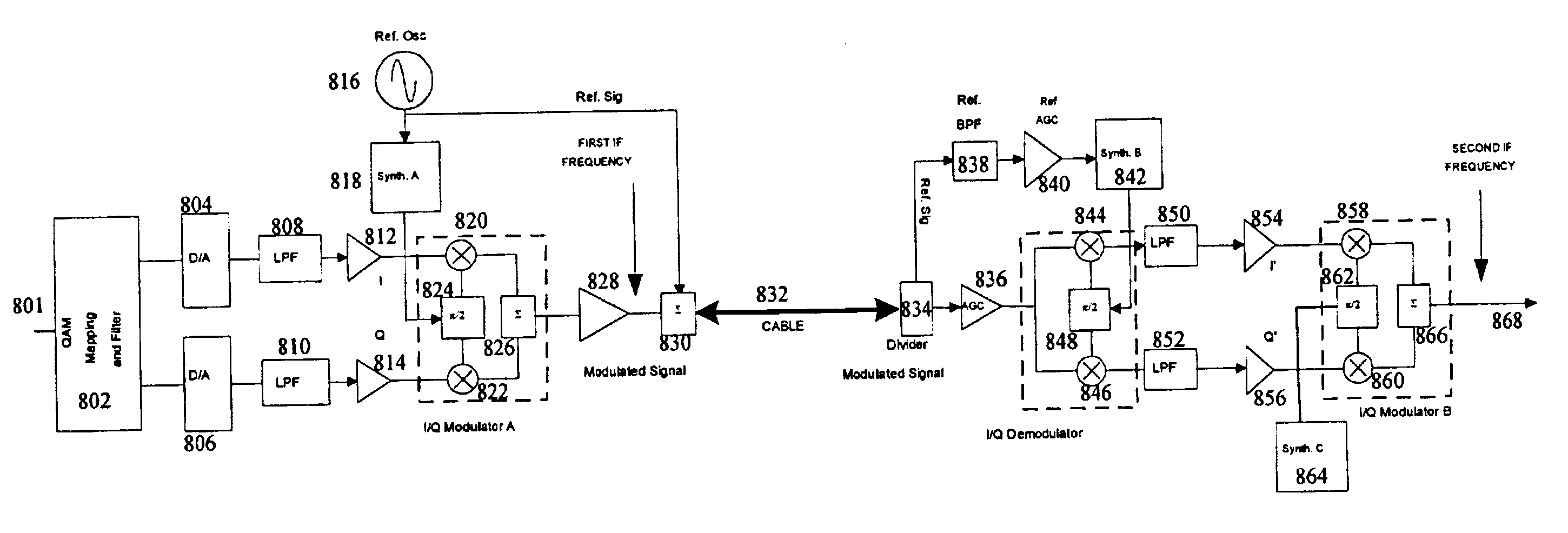
The present invention solves many of the problems of traditional approaches. In particular, the present invention provides for frequency translation of a modulated signal from an first IF to a second IF frequency without the need for image rejection filtering. Because the first and second IF frequencies can be arbitrary and no image rejection filtering is required, a wide tuning variability of the second IF can be realized which, in turn, simplifies a third conversion to microwave RF.

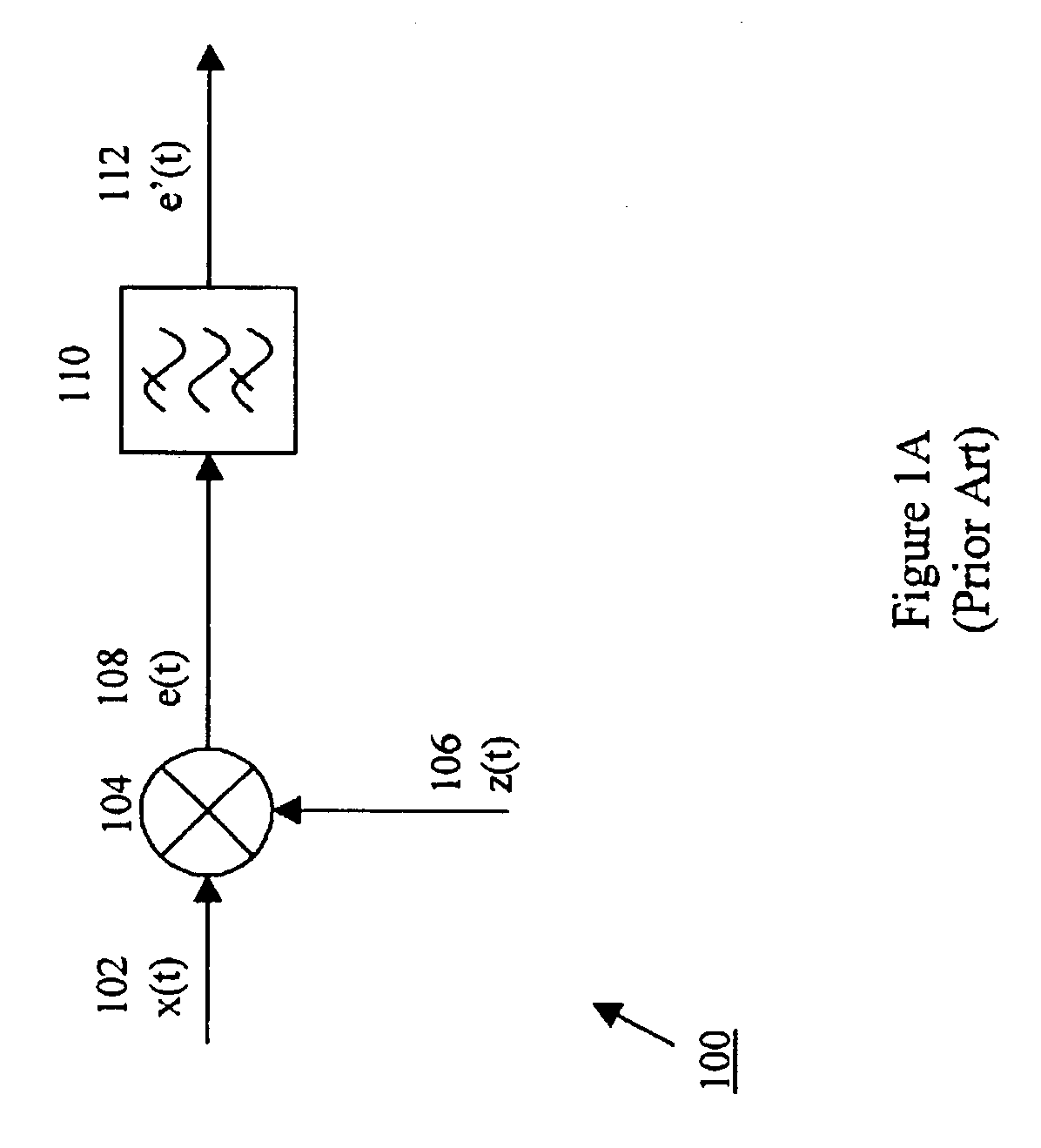
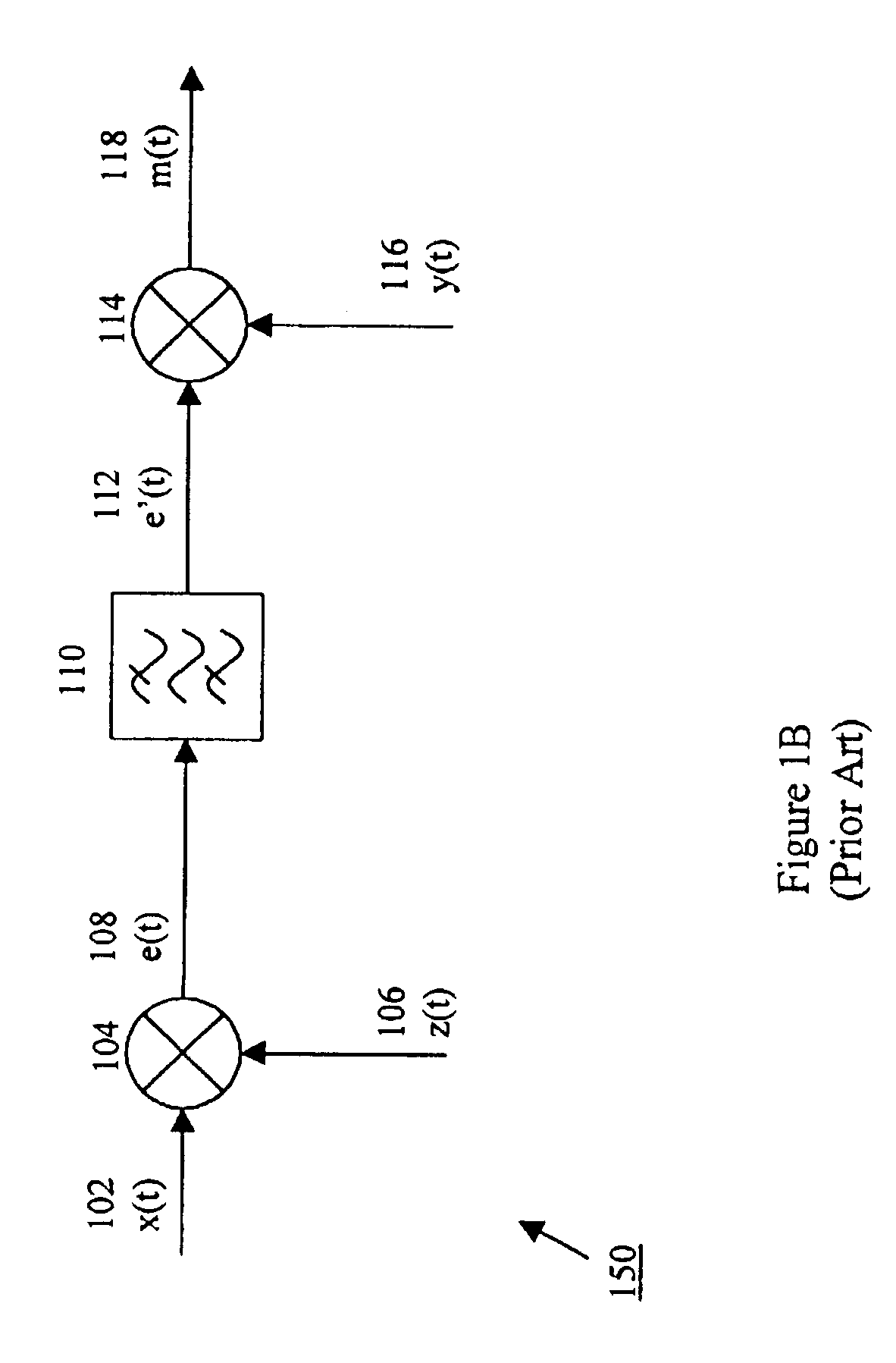
In order to understand the present invention, however, it is first useful to first understand some tuning and modulation concepts. As is well known, multiplying a lowpass signal by a high-frequency periodic signal translates the spectrum of the lowpass signal to all frequencies present in the periodic signal. Quite often it is desirable to translate a bandpass signal to a new center frequency. This process can be accomplished by multiplication of the bandpass signal by a periodic signal and is often cal...


PUM


Abstract

The present invention provides for a first modulation at an arbitrary frequency and a second modulation at another arbitrary frequency. To achieve this, the present invention demodulates the first modulation using the same reference oscillator signal that was used in the first modulation. Because modulation and demodulation are achieved using the same reference oscillator signal, a close approximation of the original signals is achieved. With this close approximation, a subsequent re-modulation can be readily achieved at a second arbitrary frequency and can further be achieved using low-cost synthesizer and modulation components. In effect, a first modulation is achieved at a first frequency; the first modulation is then demodulation to zero frequency; and, in turn, a second modulation (i.e., re-modulation) is achieved at a second frequency.

Description

FIELD OF THE INVENTIONThe present invention relates to the field of communications systems. More particularly, the present invention relates to electronic circuitry for use in modulating and demodulating digital communication signals.BACKGROUND OF THE INVENTIONModulation techniques find wide application in communications systems. In fact, modulation techniques are used to facilitate the transmission of communications signals over many mediums including wired and wireless systems. For example, modulation techniques are used to transmit communications signals over wired systems such as coaxial or twisted pair. Also, modulation techniques are used to transmit communications signals over the air such as in microwave or satellite communications. In practical applications, it may also be the case that several modulations are necessary to achieve a final result. For example, several modulations may be necessary to transmit a communications signal from customer premise equipment (CPE) to a ...

Claims


Application Information

Patent Timeline
Patent Type & Authority Patents(United States)
IPC IPC(8): H03D7/00H03D7/16H04L27/00
CPCH03D7/161H04L27/00H03D7/166
Inventor VANN, EMERICKHANTZ, ROBERT
Owner HARRIS STRATEX NETWORKS OPERATING
Why Eureka
Try Eureka