System and method for adaptive antenna impedance matching

a technology of adaptive antenna and impedance matching, applied in the field of wireless communication, can solve the problems of antenna impedance, complicated task, and decidedly more difficult impedance matching in dynamic environments, and achieve the effect of simplifying signal processing and removing transmit signal modulations

Inactive Publication Date: 2005-01-18
ERICSSON INC
View PDF19 Cites 226 Cited by
  • Summary
  • Abstract
  • Description
  • Claims
  • Application Information

AI Technical Summary

Benefits of technology

Further advantage may be gained by using a “modulatable” local oscillator circuit, such as through use of a frequency synthesizer that can be modulated. In the receive mode, the local oscillator circuit thus generates an unmodulated mixing signal at the desired receive frequency and, in the transmit mode, it generates a modulated transmit signal at the desired transmit frequency. The modulated transmit signal is fed to the transmitter, which may comprise a power amplifier circuit that provides the desired gain for the modulated transmit signal, and is further fed to the homodyne receiver's downconverter circuits, e.g., its mixers, such that downconversion of the antenna-reflected transmit signal substantially removes transmit signal modulations and thereby simplifies signal processing with respect to impedance characterization.

Problems solved by technology

While impedance matching generally offers no special challenges in environments where the parameters affecting source and load impedances remain relatively fixed, impedance matching becomes decidedly more difficult in dynamic environments, such as in the context of handheld or portable radio communication devices.
These and other actions change antenna impedance and complicate the task of maintaining a good impedance match between the device's transmitter and the antenna.

Method used


Image

  • System and method for adaptive antenna impedance matching
  • System and method for adaptive antenna impedance matching
  • System and method for adaptive antenna impedance matching

Examples


Embodiment Construction

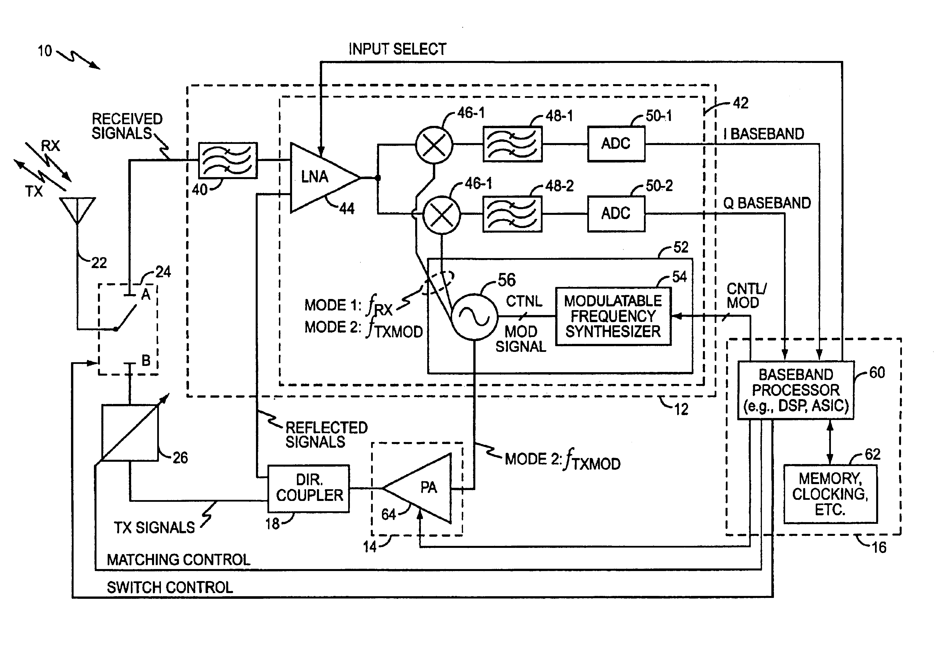
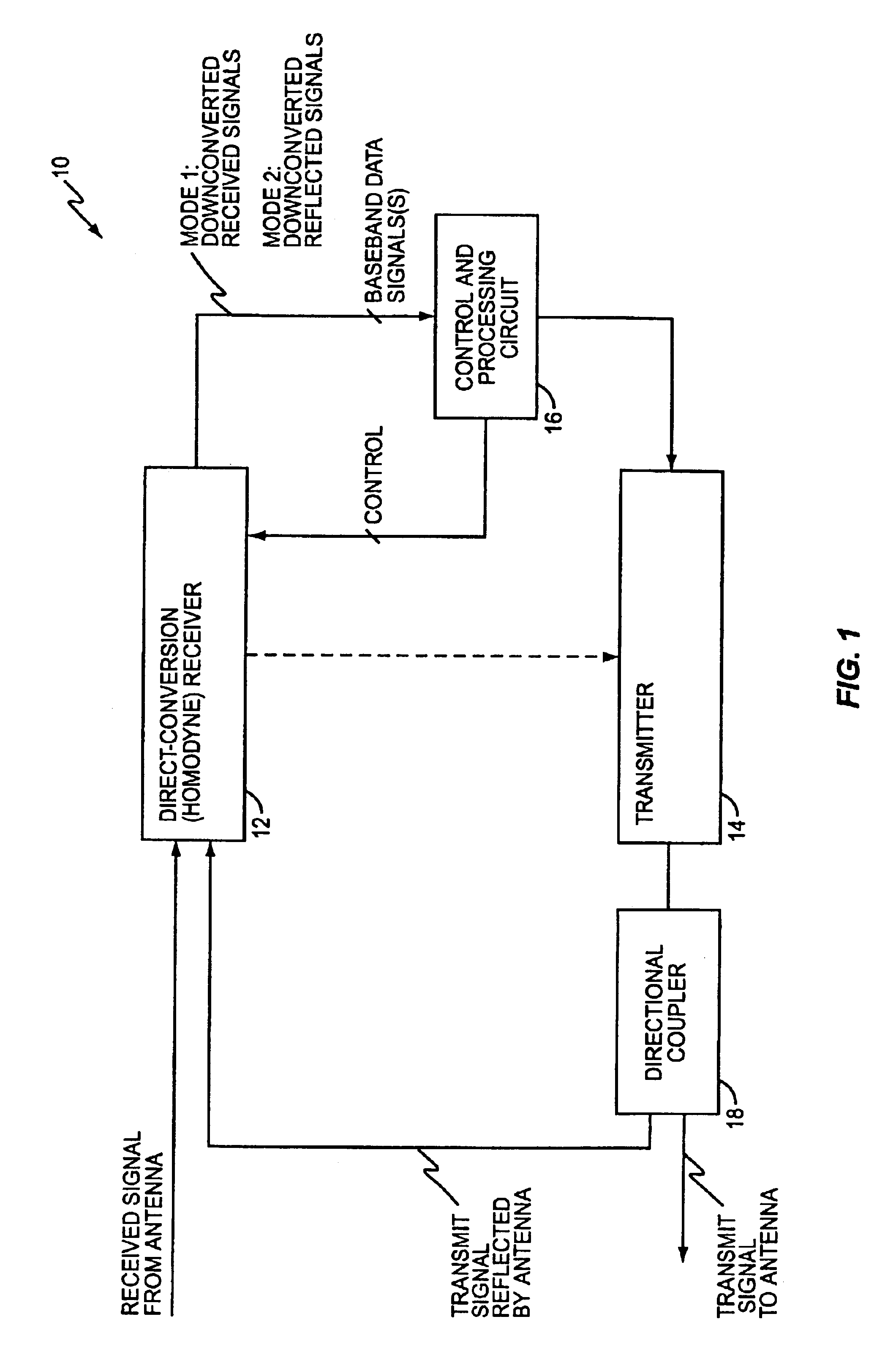
FIG. 1 illustrates an exemplary transceiver 10 in accordance with the present invention. Here, transceiver 10 comprises a direct-conversion (homodyne) receiver 12, a transmitter 14, control and processing circuits 16, and a directional coupler 18. Generally, the transceiver 10 operates in one of two modes. In a first mode, the receiver 12 is used to downconvert received signals obtained from an associated antenna (not shown) and, in a second mode where the transmitter 14 is active, the receiver 12 is used to downconvert antenna-reflected transmit signals. Thus, in the first mode of operation, the control and processing circuits 16 process the baseband signal output by receiver 12 to obtain received signal information transmitted from a remote station and, in the second mode of operation, processes the baseband signal output by receiver 12 to characterize a transmitter-to-antenna impedance mismatch.

More particularly, during the second mode of operation, the transmitter 14 generates a...


PUM


Abstract

A transceiver includes a transmitter and a homodyne receiver, wherein the receiver is used to process both antenna-received and antenna-reflected signals. Thus, during a receive mode, for example, the receiver downconverts antenna-received signals to baseband signals, which are then processed to recover receive signal information. Then, during a transmit mode for example, antenna-reflected transmit signals are fed back to the receiver, which is retuned to the desired transmit frequency, and thus downconverts the reflected transmit signals to baseband signals. These baseband signals are then processed to obtain a characterization of impedance mismatch between the transceiver's transmitter and the associated antenna. An adjustable matching network disposed in the transmit signal path thus may be adjusted based on the characterization to reduce the mismatch. Such configurations may be used with either single-band or multi-band embodiments of the transceiver, and the transceiver may be used in both TDMA and CDMA communication systems.

Description

BACKGROUND OF THE INVENTIONThe present invention generally relates to wireless communications, and particularly relates to antenna impedance matching in a wireless communication device.Impedance matching generally refers to the relationship between a source impedance and a load impedance. Maximum power transfer occurs when the source impedance matches the load impedance. For time-varying signals, matched source and load impedances also results in a minimum Voltage Standing Wave Ratio (VSWR), i.e., results in minimum signal reflections from the load.The desirability of impedance matching is so well know that it is taken as a given that one should “match” source and load impedances as part of the design effort. While impedance matching generally offers no special challenges in environments where the parameters affecting source and load impedances remain relatively fixed, impedance matching becomes decidedly more difficult in dynamic environments, such as in the context of handheld or ...

Claims


Application Information

Patent Timeline
Patent Type & Authority Patents(United States)
IPC IPC(8): H04B1/40H04B1/04
CPCH03F3/24H04B1/005H03H7/40H04B1/0458H04B1/406H04B1/0057
Inventor DENT, PAUL W.DOLMAN, RODNEY A.
Owner ERICSSON INC
Why Eureka
Try Eureka