
Configurable wavelength routing device

a wavelength routing and configuration technology, applied in the field of optical communication, can solve the problems of inflexible and/or expensive, high cost, and high cost of laying more fiber to carry additional bandwidth, and achieve the effect of facilitating lateral shifting and high degree of dispersion

Inactive Publication Date: 2005-01-18
KAISER OPTICAL SYST INC
View PDF77 Cites 24 Cited by
  • Summary
  • Abstract
  • Description
  • Claims
  • Application Information

AI Technical Summary

Benefits of technology

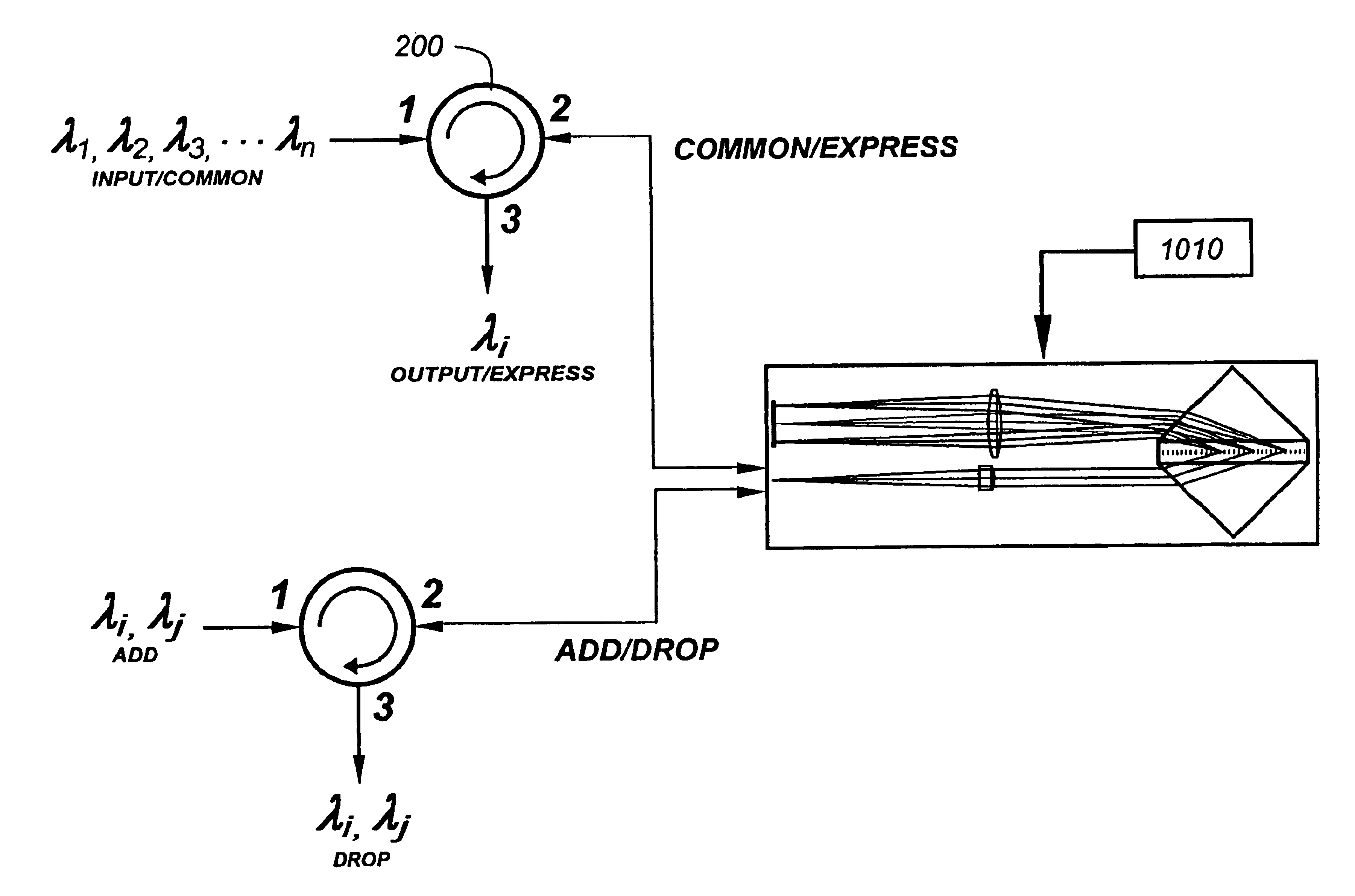
"This patent describes a device that uses a dispersive optical element and positionable micromirrors to route light at different wavelengths. The device can be used for add / drop and other applications. The input light is dispersed and imaged onto a focal plane where there are light redirection elements that decenter wavelength images on a selective basis. The decentered wavelengths are returned through the same grating and directed to points shifted laterally with respect to the input so as to implement wavelength routing or add / drop functions. The dispersive optical element is a grating or grating / prism with a high degree of dispersion that allows the input and return paths to be parallel and counter-propagating, both for a compact size and to facilitate a lateral shifting in a localized area. The inputs and outputs may be implemented in conjunction with optical fibers, in which case a lens is used to collimate light for illumination through the grating, and to focus return beams to respective inputs or outputs, as the case may be. The device includes an array of reflectors positioned at the focal plane, and a control mechanism to locate individual mirrors of the array in one of at least two positions, to effectuate the selective wavelength routing. The mirrors can be folded down to create a direct coupling between common and express ports, or placed in communication with different ports in a different position. The device can also be designed with a multi-position mirror array or an N-position mirror array to achieve more complex routing capabilities."

Problems solved by technology

The existing infrastructure of long-haul optical fiber is rapidly becoming taxed to its bandwidth capacity.
Laying more fiber to carry additional bandwidth is an extremely expensive proposition.
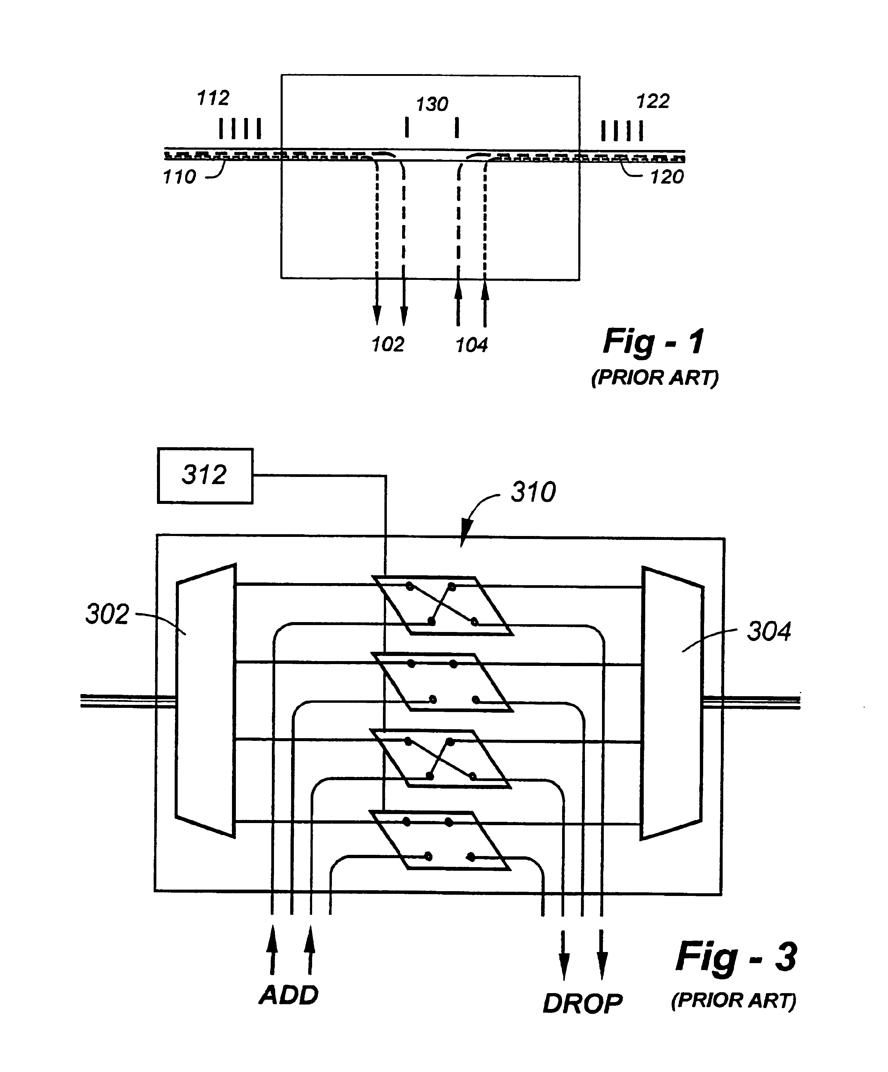
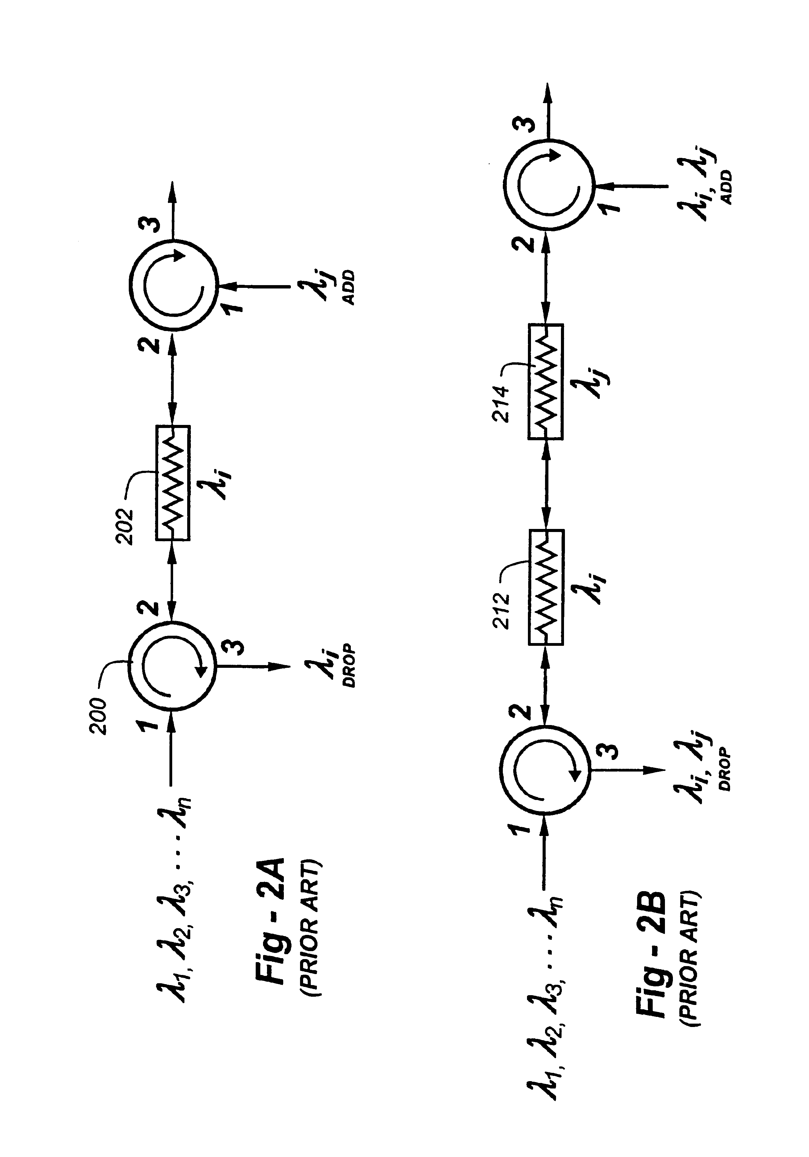
Although configurations of the type just described have been in use for some time, they are inflexible and / or expensive due to the discrete nature of the components involved.
As such, systems based on these concepts tend to be expensive to implement and maintain.

Method used


Image

  • Configurable wavelength routing device
  • Configurable wavelength routing device
  • Configurable wavelength routing device

Examples


Embodiment Construction

Having introduced and discussed certain prior-art configurations with references to FIGS. 1 through 3, the reader's attention is directed to FIGS. 4A and 4B, which will be used to introduce a novel wavelength routing system according to the invention. FIG. 4A is a top-view of the arrangement, wherein an input fiber 402 carrying multiple wavelengths is collimated by element 404 and dispersed by element 406. A telecentric imaging lens 410 is used to focus the dispersed spectrum at focal plane 412. A reflective surface such as a flat mirror is placed at focal plane 412, which is operative to retro reflect the dispersed wavelength bundle back along its original path and into input fiber 402, as enabled by the telecentric nature of the image.

FIG. 4B is a side-view illustration of the configuration of FIG. 4A, keeping in mind that the dispersed spectrum lies along a line into the paper. Dispersive element 406 preferably includes a holographically derived grating 420 sandwiched between opt...


PUM


Abstract

A dispersive optical element and positionable micromirrors are deployed to implement a configurable wavelength routing device for add / drop and other applications. Input light is dispersed and imaged onto a focal plane where there is disposed an array of light redirection elements operative to decenter wavelengths on a selective basis. In the preferred embodiment, the dispersive optical element is a grating or grating / prism featuring a high degree of dispersion allowing the input and return paths to be parallel and counter-propagating, both for a compact size and to facilitate a lateral shifting in a localized area. The inputs and outputs may be implemented in conjunction with optical fibers, with a lens being used to collimate light prior to illumination of the grating. A focusing lens is preferably used to form a nominally telecentric image of the dispersed spectrum at the image plane. A control mechanism is provided to locate individual mirrors of the array in one of at least two positions, to effectuate the selective wavelength routing. In the preferred embodiment, the mirrors are 90 degree V-mirrors, translatable within the plane of the telecentric image, such that in one position, a common port is coupled to an express port and whereas, in another position, a common port is placed in communication with an add / drop port.

Description

FIELD OF THE INVENTIONThis invention related generally to optical communications and, in particular, to a configurable wavelength routing device finding utility in various applications including use as an optical add / drop module (OADM) in a dense wavelength division multiplexing (DWDM) system.BACKGROUND OF THE INVENTIONOptical telecommunications over optical fibers is now the preferred mode of high-bandwidth data transmission in comparison to copper wire, particularly over long distances. Such systems use lasers modulated in amplitude by the data to be transmitted. The signals are coupled into an optical fiber for detection and demodulation at the other end of the link. The existing infrastructure of long-haul optical fiber is rapidly becoming taxed to its bandwidth capacity. Laying more fiber to carry additional bandwidth is an extremely expensive proposition.Dense wavelength-division multiplexing (DWDM) has emerged as a more cost-effective solution. The idea is to force existing f...

Claims


Application Information

Patent Timeline
Patent Type & Authority Patents(United States)
IPC IPC(8): G02B6/34
CPCG02B6/29311G02B6/29395G02B6/29383G02B6/29313
Inventor TEDESCO, JAMES M.
Owner KAISER OPTICAL SYST INC
Learn More