Assembly and method for cutting strands formed by thermoplastic filaments

a technology of thermoplastic filaments and cutting strands, which is applied in the manufacture of tools, glass making apparatus, metal working apparatus, etc., can solve the problems of increasing drawing speed, reducing the productivity of installation, and accelerating hardware wear

Inactive Publication Date: 2005-01-25
OCV INTELLECTUAL CAPITAL LLC
View PDF19 Cites 10 Cited by
  • Summary
  • Abstract
  • Description
  • Claims
  • Application Information

AI Technical Summary

Benefits of technology

In effect, the object of the present invention is to provide a cutting assembly which can be restarted (that is to say in which the strand can be picked up and cutting begun) without human intervention.
Furthermore, the present invention is aimed at a simple solution, involving a low number of elements, so as to have better reliability and therefore better efficiency.
This advantageously allows the wear on the anvil-wheel to be distributed across its entire width.

Problems solved by technology

What happens is that any accidental breakage of one of the strands leads to stoppage of the forming operation on all the dies, and this disrupts their operation, accelerates wear of the hardware and appreciably reduces the productivity of the installation.
Because the strand tends to follow a straight path, it soon becomes jammed between the start-up roll and the surface of the cone frustum, rises gradually up along the latter, experiencing an increasing drawing speed before finally being taken between the anvil and the cutter.
However, this device is not without drawbacks.
However, each time it is necessary to change the main cutting machine, the auxiliary cylinders have to be removed and refitted, and this is not without its disadvantages in continuous manufacture which demands a minimum of down time.
It is at this stage that there are a great many breakages and therefore a great amount of time lost.
However, this system is sophisticated.
In particular, it comprises a fairly complex restart assembly, guidance, protection and controls for the gripper which are all just as complex.
These elements are essential to the operation of the prior art, but give rise to a not insignificant restart failure rate because of the forces applied to the strand as they are set in operation.

Method used


Image

  • Assembly and method for cutting strands formed by thermoplastic filaments
  • Assembly and method for cutting strands formed by thermoplastic filaments
  • Assembly and method for cutting strands formed by thermoplastic filaments

Examples


Embodiment Construction

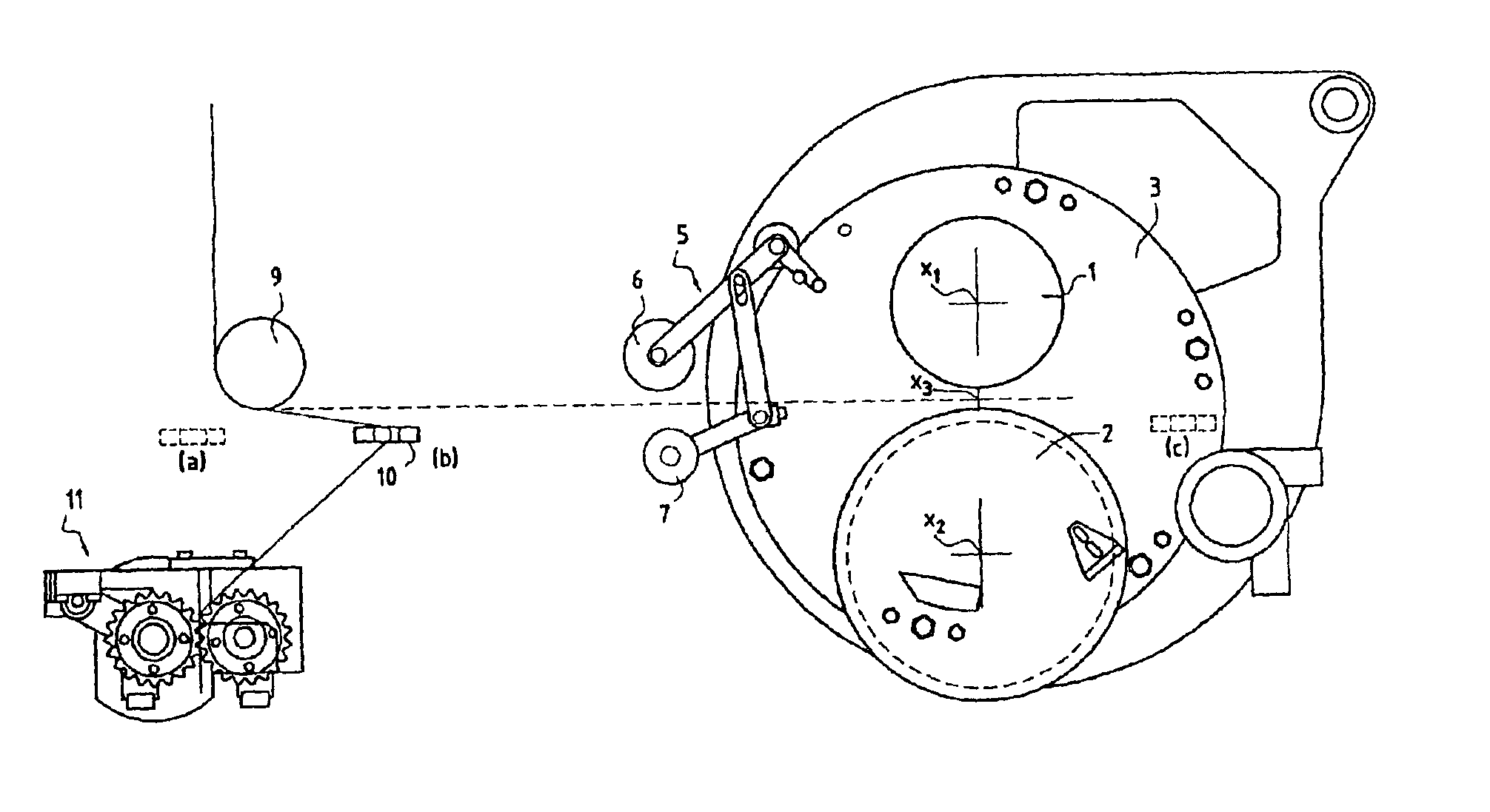
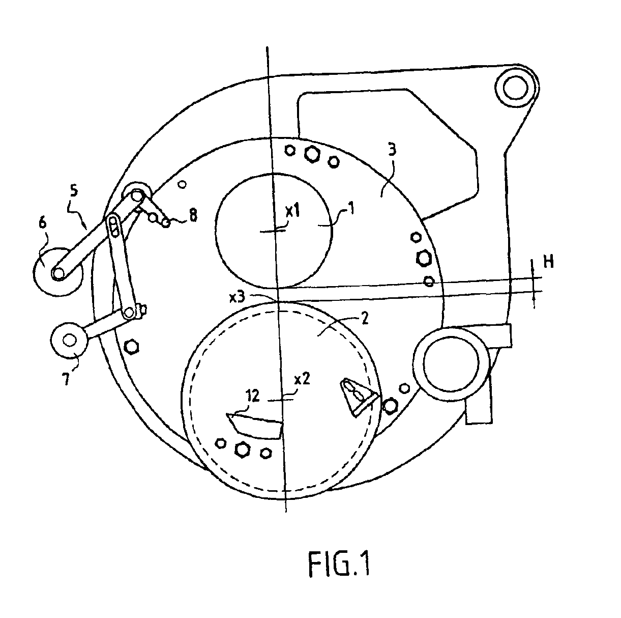
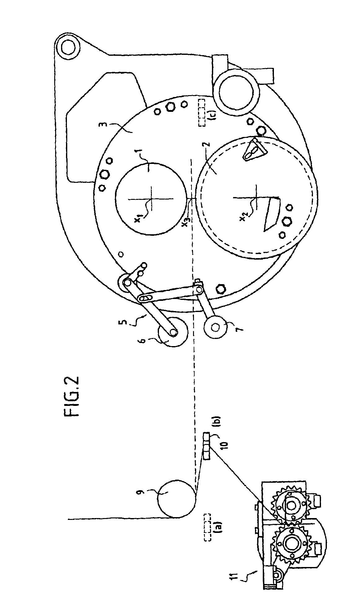
In a known way, the cutter comprises a blade-holder wheel 1 equipped with cutting blades protruding along its radii. The cutting blades are not depicted in the figures. The cutter also comprises a wheel known as an “anvil”2 the axis (x2) of which is parallel to that (x1) of the blade-holder wheel 1; when these two wheels are brought closer together, touch along their generatrices and rotate in opposite directions from one another, a cutting region is thus created.

Of course, the respective tangential velocities of the wheels 1, 2 have to be equal and the gripping torque between the wheels 1 and 2 can be adjusted to suit various cutting parameters such as the diameter of the filaments of which the strand is made, the nature of the strand, the cutting rate, etc.

Furthermore, a wheel known as a machining wheel 4 may be provided near the anvil-wheel 2 so as to grind the exterior surface of this wheel when necessary and / or possible.

According to the invention, the blade-holder wheel 1 and t...


PUM

PropertyMeasurementUnit
angleaaaaaaaaaa
widthaaaaaaaaaa
thermoplasticaaaaaaaaaa

Abstract

An assembly and associated method for cutting strands formed by thermoplastic filaments. The assembly includes a blade-holder wheel and an anvil-wheel rotating in reverse directions about two parallel axes, and at least a mechanism for actuating the wheels and for contacting a strand with the anvil wheel. The assembly further includes a mechanism oscillating the support of the wheels, whereof the axis of the support is parallel to the axis of the wheels, and an associated actuator. A mechanism for contacting the wheels is designed in particular to pinch the strand and the associated actuator for passing the strand between the blade-holder wheel and the anvil-wheel when the wheels are not in contact.

Description

BACKGROUND OF THE INVENTION(1) Field of the InventionThe present invention relates to the manufacture of strands formed of cut thermoplastic filaments, particularly glass filaments and more particularly still to a cutting method and assembly intended for such manufacture.(2) Description of Related ArtAs is known, the cutting of strands (sometimes known as threads) is obtained by passing the filamentary material between a wheel known as an anvil and a wheel known as a cutting wheel which is equipped with blades protruding uniformly at its periphery, the two wheels rotating in opposite directions to each other. The anvil wheel, generally made of elastomer of the polyurethane type, is arranged so that it comes into contact under pressure with the edge of the blades protruding from the cutting wheel, thus defining a cutting region.To keep such installations at an optimum level of profitability, it is, of course, necessary for cutting to be performed continuously, with the fewest possibl...

Claims


Application Information

Patent Timeline
Patent Type & Authority Patents(United States)
IPC IPC(8): C03B37/16C03B37/10D01G1/04D01G1/00B26D1/40
CPCC03B37/16D01G1/04Y10S83/913Y10T83/768Y10T83/0605Y10T83/051Y10T83/8804Y10T83/7788
Inventor FONT, DOMINIQUEPREVOSTO, HENRIBERTHELON, LAURENT
Owner OCV INTELLECTUAL CAPITAL LLC
Why Eureka
Try Eureka