
Motorcycle frame having removable portion

Inactive Publication Date: 2005-01-25
HARLEY DAVIDSON MOTOR
View PDF11 Cites 45 Cited by
  • Summary
  • Abstract
  • Description
  • Claims
  • Application Information

AI Technical Summary

Benefits of technology

The invention also provides a joint for fastening the removable portion to the base portion. The joint includes male and female profile end caps mounted to the removable portion and to the base portion. The male and female profiles snugly engage each other, and a fastener is extended through the joint along a fastener axis. The male and female profiles include walls that are oriented at an acute angle with respect to the fastener axis. The snug engagement of the male and female end caps and the angled engagement of the walls in the joint cause the walls to bear a substantial majority of the shear stress in the joint, and substantially reduce the shear stress on the fastener.

Problems solved by technology

Several limitations arise when a motorcycle frame is fabricated as a single piece.
While the unitary construction is generally very strong, installation and removal of the engine are often difficult, especially when it is aesthetically desirable to package the engine as tightly within the frame as possible.
Furthermore, alterations to the frame, such as relocation of the footpegs or other items that mount to the frame, can be difficult and time consuming.
For a consumer, such alterations generally require cutting, grinding, and welding of the frame, all of which may weaken the frame as well as detract from its appearance.
For a manufacturer that may want to develop an entire vehicle line using a single style of frame, such minor alterations often require expensive new tooling and / or fabrication equipment.

Method used


Image

  • Motorcycle frame having removable portion
  • Motorcycle frame having removable portion
  • Motorcycle frame having removable portion

Examples


Embodiment Construction

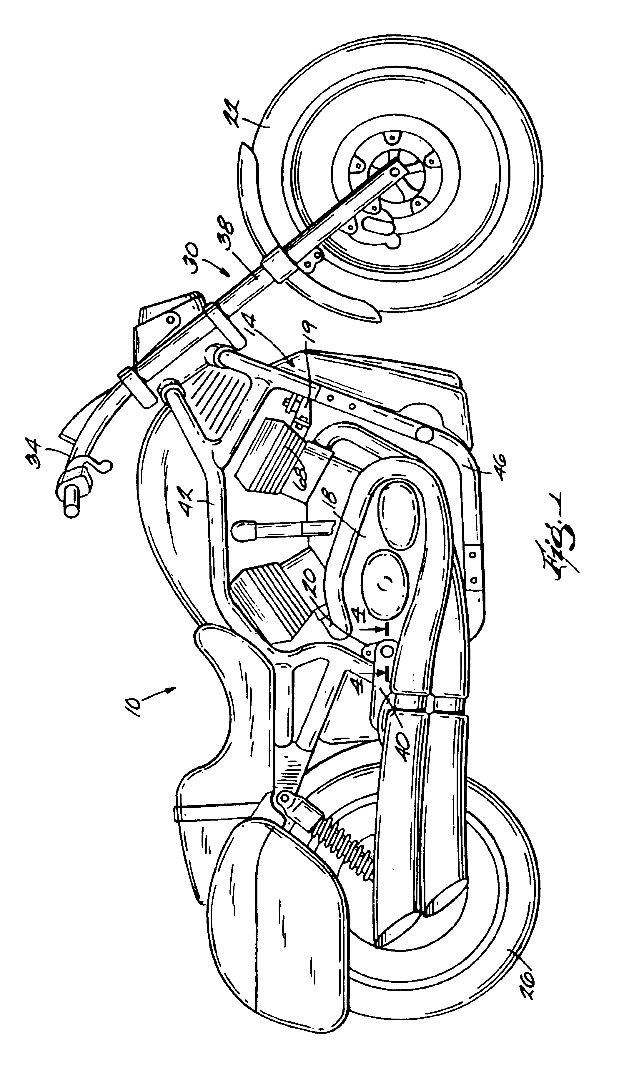
FIG. 1 illustrates a motorcycle 10 comprising a cradle-style frame 14, an engine and drive train assembly 18 isolatingly mounted to the frame 14 by resilient mount assemblies 19, 20, front and rear wheels 22, 26 supporting the frame 14, a steering assembly 30 including handlebars 34 and a fork 38 mounted to the front wheel 22 and pivotal with respect to the frame 14, and a swing arm 40 (partially hidden) interconnecting the rear wheel 26 to the frame 14. Although the invention is illustrated and described with respect to a cradle-style frame, the teachings are also applicable to twin-spar frames as well as other frame types.

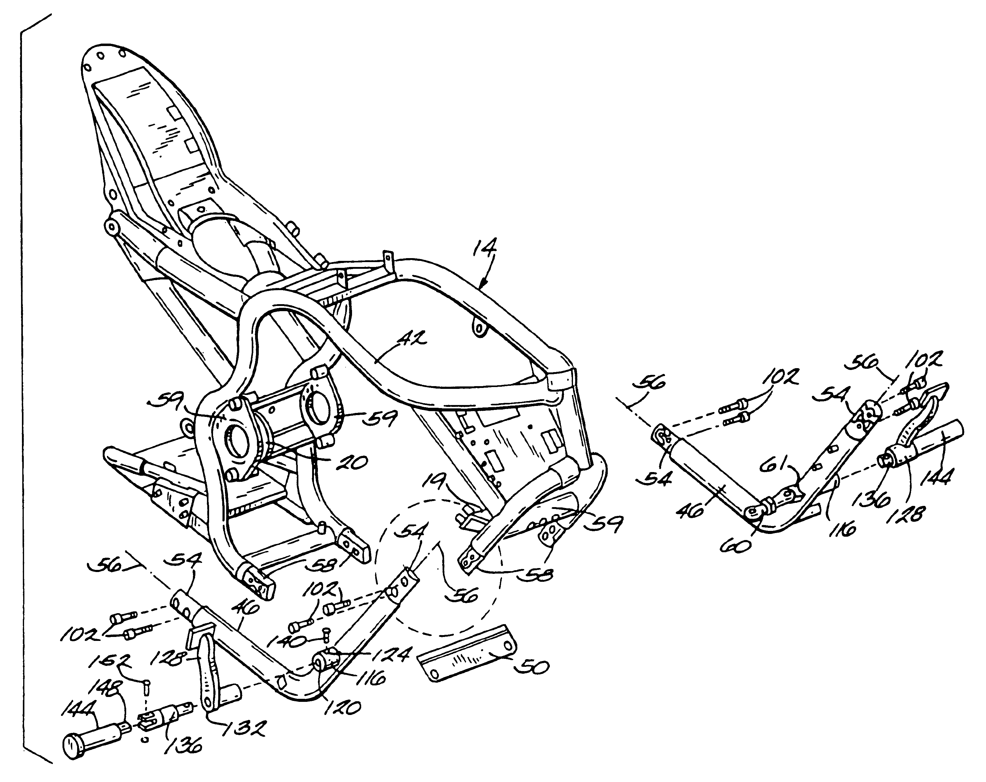
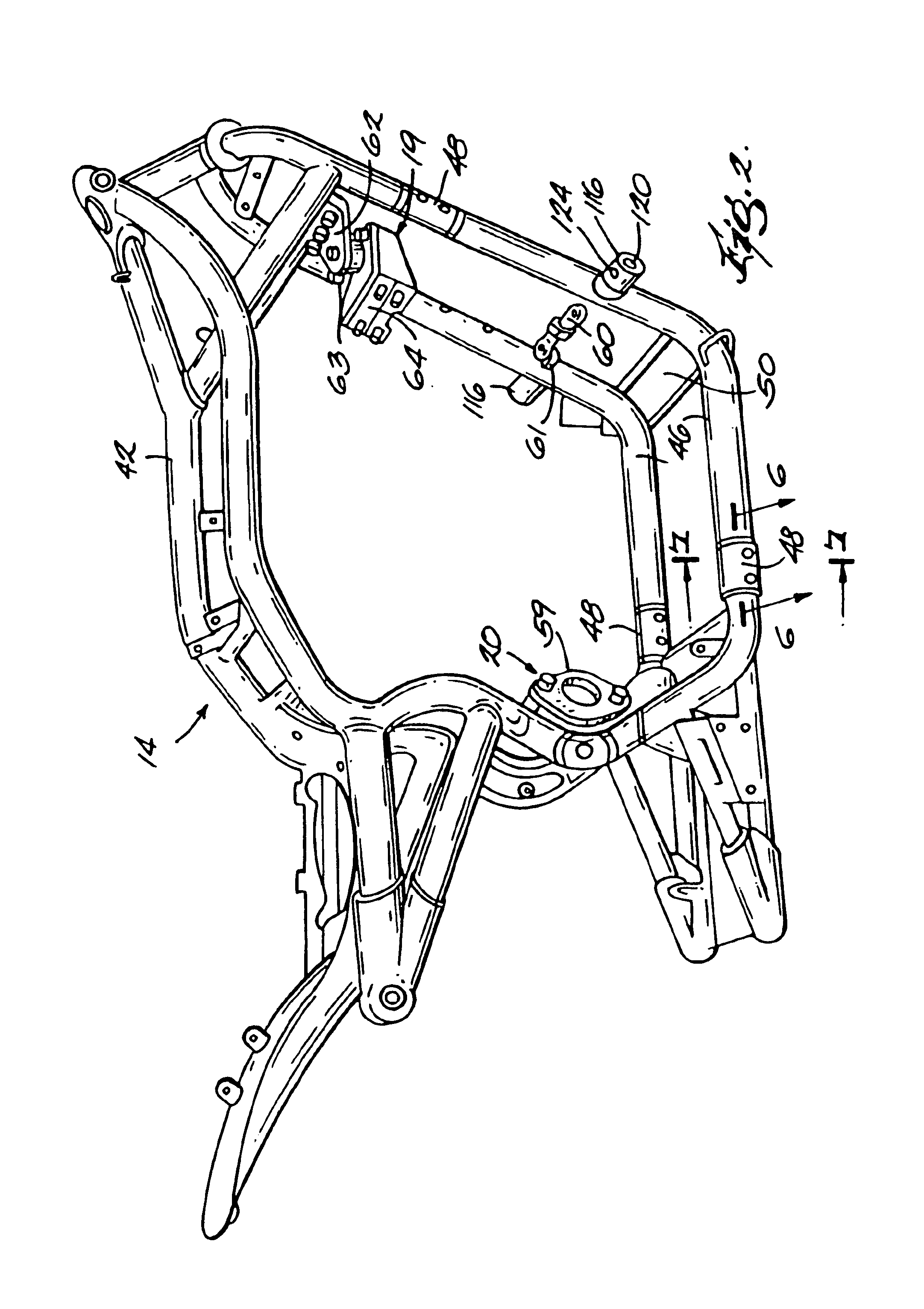
As seen in FIGS. 2 and 3, the frame 14 includes a base portion 42, two removable portions 46 mounted to the base portion 42 at joints 48, and a cross-brace 50 between the removable portions 46. The removable portions 46 are substantial mirror images of each other, except as pointed out below. Therefore, only one of the removable portions 46 will be described. Ref...


PUM


Abstract

A motorcycle frame including a base portion and a removable portion that both bear operating loads of the motorcycle. The removable portion and base portion are fastened together at a joint comprising a first end cap having a protrusion, a second end cap having a recess, and a fastener having a fastener axis and extending through the first and second end caps. The protrusion and the recess are characterized by angled walls oriented at an acute angle with respect to the fastener axis. The angled wall engagement of the end caps ensures that substantially all shear loads in the joint are born by the end caps and not by the fastener. The motorcycle footpeg position can be changed by replacing the removable portion with a second removable portion having footpeg mounting structure at a different location than the removable portion.

Description

FIELD OF THE INVENTIONThe invention relates to motorcycle frames, and more particularly to motorcycle frames having a removable portion.BACKGROUNDVirtually all motorcycles utilize some type of frame structure to carry loads encountered during vehicle operation. One type of frame structure known as a twin-spar frame typically uses a pair of large cross section aluminum beams that extend from the motorcycle steering head and around the sides of the engine to the swingarm pivot. As such, the engine is at least partially surrounded by frame structure on its right and left sides. Another type of frame structure is known as a cradle frame. The cradle frame generally includes one or more structural members extending over the top of the engine, and one or more structural members extending below the engine. Both types of frames support a wide variety of motorcycle components including the engine, fuel tank, seat, and footpegs, as well as other items.Most motorcycle frames, whether twin-spar ...

Claims


Application Information

Patent Timeline
IPC IPC(8): B62K19/00B62J25/00B62K11/02B62K11/04
CPCB62K19/00B62J25/00B62J25/06B62K11/04B62K2015/001
Inventor DENNERT, ROBERT L.DENNERT, R. BRUCELOHR, PAULHAMANN, MICHAEL W.
Owner HARLEY DAVIDSON MOTOR
Learn More